160 Inverted L Antenna

160 Inverted L Antenna – by N4JTE.

Between watching unending Law and Order repeats and the XYL’s Lifetime movie sagas, compounded by a dead 40 meter band here at night, I became so totally bereft of late night activities that I got the bug to get back on 160 meters again with something that would fit in my backyard. I have had, in previous QTH’s, the luxury of a full size 160 dipole, those were the days.

Well, 240 plus feet at any reasonable height is beyond my backyard limitations as I am sure it is, along with many of you. The 160 band is to me, a throwback to my AM and SWL days as a youngster when I would lay in bed at night with my crystal radio and listen to all the AM broadcast stations I could discern and check them off on my Knight’s Radio Log. Those days, are to me, the genesis of my love for the magic of radio, some of those AM stations are still legendary! Enough nostalgia.

I wanted to get back on the band with a respectable signal and try out the much discussed and prevalent 160 inverted L antenna. Previous to the inverted L, I tried a few ideas, some of which I am sure others have attempted also.

PREVIOUS ATTEMPTS:
1; 80 meter dipole, coax fed. Whew, lucky I did not burn something up, I know why it stunk but there are still some out there that figure if their good old trusty tuner loads up and somehow a length antenna seems too work on 160 they are good to go, NOT! Besides the neighbors getting tvi, your tuner and feedline were probably contributing to global warming.

2; 165 ft. 40 edz at 60 ft. ladderline fed. I really thought this antenna would work as its only 60ft. short. The fact was that my 3kw tuner told me that with anything over 100 watts, I was dreaming, as Christmas came early with all the flashing lights inside the tuner.

3; The good old G5RV with the shorted feedline and ground plane approach. I’m sure I remember a contact or two on a quiet night but pretty lame imho.

0x01 graphic
160M Inverted L .

There are a lot of 160 designs out there on the internet with quite a few adding coils etc to match shorten verticals, or top loading with various configurations. My feeling is that the coil losses and tricky matching problems with top loaded wire antennas make the inverted L the way to go for simplicity of construction and relative ease in matching 50ohms.

The inverted L is what it is; picture your Hamstick or any vertical and bending it 90 degrees halfway up and expecting some improvement over a nice simple straight vertical. Let’s be aware of the physics involved and keep our expectations within reality.

But: That’s the mystery and fun unique to the 160 band, anything that approaches a well thought out antenna, even in a restricted place will compete well. The really big guns with the phased 120 ft towers and 4000 buried radials only show up for the contests. The rest of us peons have a pretty level playing field when we are content to work a new state or keep in contact with friends around the country, with the occasional DX station popping in to say hello.

THE CONSTRUCTION:
The best I could do here was to get the old trusty 2oz weighted fishing line over my now bare 65ft. maple tree. Hobby money is tight here so I scabbed together 120 ft of insulated # 14 wire form previous endeavors and pulled back some masonry line. Taking care to keep the ends from tangling, the string was attached to the 60 ft. midpoint of the insulated wire and hoisted up to the top of an outside branch on the tree with the feed point end about 6 ft. off the ground.

FIRST ATTEMP:
Because I had nothing better on first thought and it was getting dark I ended up having to slope the remaining 60 ft. to a tie off point in the backyard which resulted in the end at about 10 ft. off ground. I hooked up two raised insulated radials at 120 ft. long each and hung them up at 6ft. high along the wood fence. Definitely not as symmetrical as I would have preferred with some zigs and zags thru the available branches etc. but ran them at 180 degrees from each other. Be advised there will be a lot of voltage on the radial ends and make a supreme effort to isolate the ends from any human contact.

RESULTS:
Not bad, first of all the amp, AL80B, was finally showing some life and providing 400 watts indicated. Reports were good from local to 1500 miles out but the S/N, noise was horrendous, so I figured it was time for some improvements.

SECOND ATTEMP:
Well, I was happy to be heard and the amp and 3kw tuner were silently applauding my work so I figured lets work on the noise situation. I figured out a way to get the horizontal portion over a nearby tree at about 45 ft. high, and try to get closer to a flat top configuration, but unfortunately it is only about 40 ft. away. End result was that the last 20 ft ended up coming down in a vertical direction to the tie off point, sorta ended up with a skewed inverted U configuration.

Voila! Ended up with a relatively flat 1.5 to 1 on 1865. I know that can be misleading, especially when using a bizarre shaped vertical, but it works. See note #5 in final comments.

FINAL COMMENTS:

1; If you are in tight restricted environment, the inverted L will get you on the air with a respectable signal and good match to 50 ohm coax.

2: Yes it will be noisy in an urban near field environment; I use my 40 meter antenna as a listening antenna when my local noise competes too much.

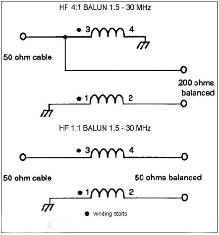
3; I placed a 1 to 1 current balun at the feedline junction; I did not see any significant noise reduction.

4; From talking to other Hams more advanced and experienced with the 160 inverted L, I found a few that liked the 3/8 wl configuration as it moves the current point further up the antenna and improves efficiency beyond the 28% we can expect from the inverted L. However I believe the 3/8 configuration is adding more horizontal polarization as a trade off for better efficiency which is fine if your interests are more in line for closer in contacts. I don’t see any major signal loss on close in stations but the inv L definitely shows it’s worth beyond 800 or so miles, (whose counting ?) as compared to a 165 ft. flattop at 60 ft.

5: If you build it, I offer the following insights from my experiment. Going the raised radial route is the only way I could consider this or any vertical design with my rocky conditions, your mileage may vary, but read up on them. If you do use raised radials make every effort to run the feed line away at a right angle if possible, mine isn’t. As mentioned, a 1 to 1 current balun is a big MUST; it will reduce any stray induced current on the coax shield.

My MFJ analyzer indicated 40 ohms resistance and about 1.2 to 1 swr. Anything way above or below that number should tell you that your ground plane is inadequate or you have common mode current problems. To achieve your best match, prune the horizontal section length.

Lastly, the hard part, try to make the vertical section as tall as possible and if you are concerned with a DC path to ground while using elevated radials, throw a choke between the coax shield and the ground rod or equivalent. Do not just hookup the coax shield directly, unless you like talking to worms.

FINAL FINAL COMMENTS:

The setup as laid out in this article is working than better than expected and has reawakened my appreciation for the challenge and fun to be found on the 160 meter band. It is noisy at times here in upstate NY with my backyard surrounded by commercial businesses and transformers for the extended care facility 100 ft away, (there, but for the grace of God go I) so I use my flattop 40 as a backup receive antenna when it gets too annoying.

Try it out, the inverted L is as cheap as it gets and will give you a horizontal and vertical sky wave easily matched to coax. Definitely more entertaining than the Lifetime Channel!

Don’t forget; 160 meters separates the men from the boys, see you there!

Tnx for reading,

Bob, N4JTE

Back to top^

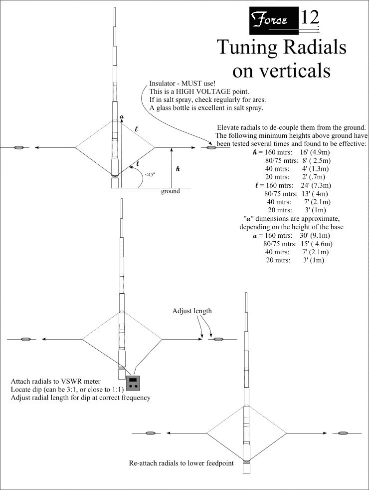
Tuning Elevated Radials

Tuning Elevated Radials for 1/4 Wavelength Verticals

Verticals for the low bands have classically been an electrical 1/4 wavelength long (tall) and require a radial system for the current return. The exception is the vertical dipole, which is now more commonplace since the development of the SVDA antenna system (see the write-up on K5K) and the new SIGMA series vertical dipoles from Force 12, Inc. When using a 1/4 wave vertical, laying 120 buried radials (as indicated in texts for decades) is rarely practical for most of us; therefore, a different, but efficient approach is needed.

The original concept was discovered in an I.E.E.E. article some years ago where the buried radial systems on commercial AM broadcast antennas were disintegrating over time. Adding elevated radials was shown to be extremely efficient and a practical solution for the current return. The concept was put into practice on our first trip to Jamaica for the A.R.R.L. competition as 6Y4A. It has been used on every installation since that time and on many other installations world-wide.

We had carefully selected the 6Y4A operating site, which was right on the ocean with several hundred feet of beach available for vertical antennas. One of the first antennas we installed was the 160 mtr vertical, followed by the 80 mtr verticals. Since we were on the ocean, we laid the radials on the “ground.” This consisted of a combination of rock, salt water and grass, all right adjacent to the ocean. Conventional “wisdom” would say we had done a wonderful job – hardly. We were unable to have anything close to a 1:1 VSWR, nothing less than 2:1 at best. The team looked to me for an overnight solution (didn’t get much sleep) and my memory was working well enough to recall the I.E.E.E. article. After not much sleep, we got up early and did an important test: when we added the hairpin match to increase the feedpoint up to 50 ohms, the VSWR got worse.

The feedpoint for a full size 1/4 wavelength vertical should be in the low 30 ohm range. Shortened verticals are lower, often in the 12-20 ohm range. We were using physically short verticals with efficient linear loading to load them to an electrical 1/4 wavelength, with an expected feedpoint of less than 20 ohms. When we added the hairpin to transform the feedpoint impedance higher towards 50 ohms for an acceptable match, the VSWR got worse. This meant the feedpoint was already above 50 ohms, which was caused by the added loss (resistance) of the ground. We now knew the problem and we quickly worked out the “gull wing” elevation technique for lifting the radials above ground. As soon as the radials were in the air, the feedpoint impedances became acceptable. It should be noted that even with the poor match (and high losses) we did use the verticals that night, with excellent performance, due to the proximity of salt water. After reducing the losses by elevating the radials, they were even better.

A procedure was developed over the next year to elevate and tune radials. The drawing above shows both the basic technique for elevating radials, as well as the height above ground for effectively de-coupling the radials from the ground.

Any questions or comments, please zip off an e-mail to us at [email protected].

73, Tom, N6BT

Back to top^

Tower Safety by N6JSX

Tower-Party Safety by Dale Kubichek  N6JSX /8

The ultimate achievement, the status flag, the pinnacle of being a HAM is when you operate from your own tower. Whether the tower is to raise the apex of a HF inverted V, obtaining increased repeater/ATV distance, or optimize HF beam antenna height – height will improve your ability to make contacts.

This article is not about lightning nor grounding, this article is about YOU a HAM that has little to NO background in tower climbing or antenna installing – the classic out-of shape nerd that thinks he can do anything and will try to prove it. But all too soon you will learn the perils of heights when hanging from the tower for needless hours while attempting to install a tower section, antenna, rotor, or other items to discover you’re missing a part or tool. Then the ground crew is sent scurrying about seeking what is needed to make the tower-party evolution a success while you hang aloft – is that SAFE?

When it comes to having a successful tower-working-party, it is ALL in the planning, planning of each mundane detail with contingencies, alternatives, or enough information to call a delay until all is right! The number one goal to ALL tower-parties is to achieve SAFE success. The tower owner will lead or designate a leader that needs to create a written tower-party PLAN (a script) for all in the tower-party to reference. Write the PLAN like a choreographed NASA step-by-step space mission.

In the PLAN, do not bite off more than you can chew – plan to complete only one task per tower-party. Consider yourself lucky (or well prepared/experienced) if you’re able to get to task number two before the tower climbers must come down. ThePLAN needs to be written breaking out each task. ONLY progress to the next task when all agree (including climbers)! Party Chief remain aware of your climber’s fatigue while aloft – talk to them often to judge their state, but try not to frustrate them too much as they need to focus on the job at hand!

A good PLAN will select a cooperative and talented ground crew! Tower items should be pre-group on the ground for ease of access, pre-assembly, pre-tuning, and to insure all mounting hardware is present and kitted. Then insure you have the right tools for the job – double check everything ‘before’ the climb!

Just before the climb the Party Chief, Lead Climber and Ground Commander ‘shall’ conduct a party SAFETY briefing and verbally read the PLAN to the party (as a walkthrough) answering all questions NOW – not later – before anyone climbs. Insure everyone in the ‘party’ is thinking alike! Anyone in the tower- party can yell “)STOP)” if any safety hazard is spotted at any time (in this, all are EQUAL)! Make NASA proud – lives may depend on your eyes and actions.

The biggest uncontrollable factor to any tower-party is the “WEATHER!” COMMON- SENSE rules the day on this subject! If you decide to climb a tower with rain or thunderstorms near, I’ll read about you getting a Darwin award. Remember, lightening can strike even in clear skies up to 20 miles in front of a storm. But when it comes to tower work the unrealized killer is WIND, wind will swiftly fatigue even the most fit tower monkey (climber) with sun beating HEAT running a close second. If you climb with wind chills below freezing you deserve a Darwin award!

Topics for the tower PLAN: (but not all inclusive)

Purpose/leaders:

Tower build/repair – tasks #…

Rotor placement/repair – tasks #…

Antenna placement/repair – tasks #…

Annual maintenance inspection/repair – tasks #…

Who’s the tower-party Chief that makes all the calls: _call sign

Who’s the lead Climber who makes all calls aloft: _call sign

Who’s the ground Commander who makes all calls below: _call sign

Weather:

Season temperature – expected OP window hi:___ lo:___

Season winds – expected OP max:____mph

Season wind direction – no go direction:____

Season sun/rain/lightening/snow/ice/fog/etc

Emergency:

Site electrical/telephone wires – proximity safety review

Who will administer: _call sign(s)

First aid

CPR

911 – who will make the call: _call sign

Tower:

Climbers – abilities/experience/stamina

Climber’s harness/Carabineer/belt/hooks/ropes (safety inspection)

Gin pole & ropes

Rotor, cable, brackets, hardware, sealant

Tower parts/hardware

Tools:

Ladder (if used, pre-use safety inspection)

Common multi-purpose hand tools/wrenches

Special tools need/availability/how used

Tape/tie-wrap/lubricant/grease/etc.

Tender bucket for Tools/H2O/etc w/hoisting rope

Antenna #1:

A detailed list of hoisted assembles & discrete support hardware

Pre-assembled & adjusted (on the ground)

Verify all mounting hardware is present / kitted

Coax & connectors

Order of hoisting / tower placement (insure within climbers reach)

Mag or True North – how aligned

Antenna #2, #3…:

Same as Antenna #1

What if’s:

Missing / dropped / lost hardware contingency plan?

Who on Ground team assigned to run for hardware?

Tower-Party items to consider:If you’re erecting a tower or hoisting more than 25 lbs onto the tower use a ‘gin-pole’. A gin pole is a type of crane arm that is temporarily affixed to the tower. This arm has a pulley and rope for hoisting. Use the ground team as the mules (with leather gloves) – the climbers aloft do NOT hoist, they guide items aloft!

Often you will need to pre-assembly the tower mast with the top antenna(s) with coax attached. ALWAYS use a second rope as your guide rope to keep the load away from the tower to insure no snagging of tower rungs. These items get very heavy and cumbersome and just a little wind can double or triple the load complexity making the lift unwieldy! Climbers should never try to be King-Kong by man handing the load aloft, let the ground carry the loads weight via the gin-pole rope. Climbers, it is so very easy to pinch a finger or drop the load onto a finger or hand while aloft; do not forget to watch for the unpredictable devilish helper THE WIND. Rhetorical climbers; how do you get down with a damaged wing that is bleeding onto the ground crew? Climbers need to be conservative in their approach aloft to remember to position yourself away from the load IF it drops it does not drop on you!

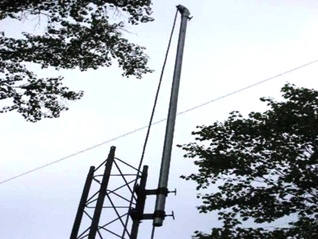
Gin-pole in place on a Rohn-25G tower section, notice the rope comes down through the pipe/ pole!

(Shown without crotch straps rigged)

Klein Lanyards #SPA-496

BlackHawk!™ Lanyard #990453OD

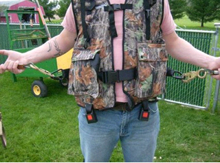
Safety requires a climber’s harness has independent (two) lanyards; it is essential the lanyards have self-locking Carabineer/hooks. Having independent Carabineer/hook lanyards will keep you attached to the tower at all times while you ascend, descend, or adjust your position.

http://www.service.kleintools.com/

http://www.blackhawk.com/product/Personal-Retention-Lanyard,1088,1390.htm

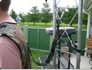
I had used a climbers ‘waste’ belt for years but it often would slide up my mid-section creating severe back strain. Upon returning to the Midwest and becoming an Ohio DNR Hunters Ed Instructor, this old dog learned a new trick. I acquired a full body tree-stand hunting harness that has a built-in waist-belt with D hooks for lanyards. This is by far much more comfortable and safer! My son is wearing my vest-harness for the pictures. This vest is similar to “Big Game® EZ – ON Safety Vest” a TMA-certified Safety Harness for ~$60 (what is your life worth?) http://www.sportsmansguide.com/net/cb/cb.aspx?a=991940

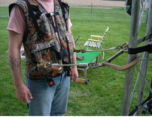
An added benefit of using a hunter’s tree-harness is it has a safety tether in the center backshoulders where a ‘real’ mountain climbers Carabineer is used to hook the harness onto a tower rung (or looped around a fat rung using the Carabineer to reattach to the strap).

As pictures the “Hunter Safety System® Carabineer” is an aluminum alloy rated to 5,600 lbs, w/large knurled auto-locking nut costs ~$10ea. Do NOT use cheap key-carabineers’ from hardware stores that are not rated for any real weight nor strength – what is your life worth? All Safety ‘Carabineers’ should meet or exceed ANSI Z359.1, CSA Z259.12-01, EN 362:2004B and 100% proof loaded to 3600 lbs, min breaking load >5000 lbs.

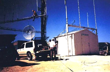
(That’s me sitting on the 20’ cross member of the 100’ tri-array)

[Side story: We started out on a bright sunny day in 1988, to install a 220 remote base repeater system on Sunset Peak 5,600ft (just below Mt Baldy 10,900 ft) above the San Gabriel Valley, CA. We were on a 100’ tri-tower complex for hours when unexpected weather blew in. We were caught in thick fog (low clouds) that zeroed our visibility of the ground crew and then it turned into a blowing rain then to snow (blizzard). Since I was the only one with a two lanyard-belt I sent the other two below. During my hour descent I had to install all the hard-line clips and by the time I got to the ground my right side was a sheet of snow/ice. Do you know how slippery soaked leather gloves become on freezing galvanized metal? I religiously and slowly descended one rung at a time always re-hooking into the tower after every rung! As they say _hit happens BUT we did not check the WX before climbing as it was bright-n-sunny when we arrived – see picture!]

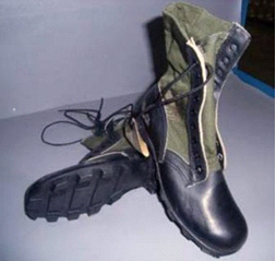
From years of experience and lessons learned – I highly recommend climbing with good boots. Putting all your weight on the Rohn-25 quarter-inch wire rungs really hurts in a very short time. If you are working on Rohn towers you will want solid shank boots. Old style Vietnam jungle boots with punji-stake steel bottom inserts works fine and these boots are still relatively cheap through surplus stores. Rohn-45/55G rungs are not horizontal but angled making your foot slide to the tower sides wedging your foot becoming quickly uncomfortable and even slicing your boot soles. http:// www.armynavysuperstores.com/jboots.htm

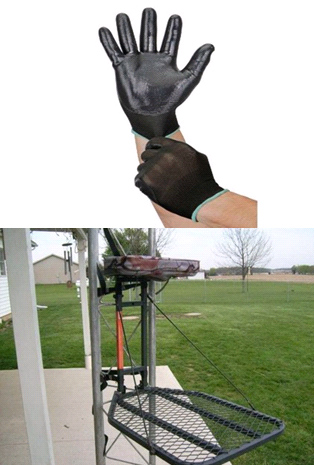
Never climb a tower without wearing leather gloves. The metal temperature can cause hand cramps, sliding your hands over metal burs will ruin your day, as well as bird stuff, rust, and flaking metal can make for slippery hand holds. Once you’re at the tower working position you may want to change your gloves to a thin rubberized skin workman’s type glove to improve your dexterity for tools/nuts/bolts!

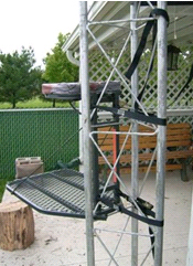
Since I’m not getting any younger (or lighter) I find tower work more tiring than 25yrs ago. Standing on tower rungs hurts in time even with solid shank boots. What is needed is a standing platform to ease my discomforts and prolong my time aloft. Most tower companies sell platforms but are cost prohibitive and the platforms have a very small foot area. Since I’m a hunter and hunting tree stands are made to hold me aloft for long periods I gave it a try. I bought an economical ~$50 tree stand, to be my tower platform and it even has a seat so I may take scenic rest breaks. It does not get much better when relaxing on your tower top looking at your installed antennas or taking in the local vistas!

This may not be the conventional way of using a tree stand but the mechanics are nearly the same. If you decide to use a tree stand on Rohn-45/55G test it at ground level first to insure your tree clamping straps will reach and to verify your stand mounting strategy.

I placed the stand onto the Rohn tower and used a pre-sized bungee cord with hooks to temporarily hold the stand to the tower while I thread the retaining straps through the hand pump-lever winches. You MUST use both stand straps! The top will get most of the leverage from your weight but the bottom strap insures the stand will not kick out from the weight supporting rung. The straps only need to be snug but firmly in place to insure minimal movements of the stand. Beware of the platform cables as they can snag your boot – since you’re still harnessed in snagging this trip hazard should only momentarily get your heart to skip a few beats, but I’ll leave to your imagination what color your shorts have become.

Notice the bottom of the stand platform bracket is resting on the tower wire rung.

NEVER drag equipment up with you while you’re ascending, it may get snagged in a tower rung and the extra weight will accelerate your climbing fatigue much faster. The only item you should bring up with you is a rope that will easily reach the ground.

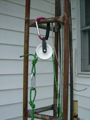
My Tenders (5gal) Bucket rig

There are a few methods to rig a tender rope, the simplest is to use a tower rung but it creates a lot of rope friction so I made my own Tender rig (pictured above). A Harbor Freight big Carabineer attached to a simple plastic pulley that runs a >¼” rope. My tender rope has two Poacher’s knots, one on each rope end that is connected by the same Carabineer. The Carabineer allows easy attachment of a Home-Depot™ 5-gal tender bucket that will hoist all the tools/water/towels/etc aloft. This rope method makes a complete loop and allows the noload rope to be used as a guide-rope keeping the bucket from snagging the tower.

If I’m installing a rotor or needing to hoist items larger than my tender bucket I will install my Tender outrigger arm. The arm keeps the tender bucket/load away from the tower. This home-made arm is 2”x1/4” steel angle ‘L’ about 4’ long; holes are drilled to allow attaching ¼”x20 ‘U’ clamps (TV mast type) to the tower vertical pipes. I use ¼-20 wing nuts on the U clamps to lessen my tools aloft. The other end of the outrigger arm is a hole to hang the tender rig.

Remember, to ALWAYS have a guide rope on any load going aloft. The guide rope is used to keep the load away from the tower so nothing snags the tower, guy, or electrical wires – but remember to insure the climbers can untie the guide rope. I’ve seen guide rope attached to the reflector/boom end of a HF yagi beam to only discover there was no way to untie the rope when it was installed in place – this mistake usually only happens once!

There is ONLY one ground Commander while the monkey(s) are swinging on the tower, period! The Commander issues all hoisting commands (getting queues from the Lead Climber) while all others on the ground are quite mules. This is not the time to argue or have turf battles. During the pre-evolution Safety briefing a clear chain-of command was established! This may seem harsh and overly bearing but this tower evolution is all about success and SUCCESS MEANS SAFETY — a boisterous or arguing ground crew is unsafe!

In the purest of safety methods every tool has a tether string tied to it. But this is not practical. I found a different method – using two magnetic tool strip holders (bolted back to back) to easily hold tools aloft. I place the strip onto the tower and ONLY use it to hold my ‘actively’ in-use tools. (I move all unused tools to the tender-bucket as soon as possible.) Another handy use is to hold steel screws/bolts/nuts/washers until needed! http:// www.harborfreight.com/18-inch-magnetic-holder-65489.html ~$5ea.

ABSOLUTE RULES for ground crews are to wear eye protection; safety glasses are the best but sunglasses at a minimum. If you’re a ground crew member getting closer than 25’ to the tower you should wear hard a hat, as stuff falls much faster then you will hear someone screaming “incoming”. A falling tool can bounce off tower rungs and fly! CLIMBERS, if a tool (or anything) is dropped immediately scream “INCOMING” or the attention word(here is where a four letter word may be appropriate) to get all to look up and duck-n-cover.

Needless to say, beer/booze is for AFTER the climbers touch the ground!

I’m sure there are many more items to be considered, this article is only a starter to get you thinking. I hope this article helps your next tower-party; if it prevents an injury or saves a life it was worth my time in writing and your time in reading!

Writer BIO: Dale Kubichek, BS/MS-EET, GROL/RADAR, N6JSX – Amateur Extra; first licensed in 1972. Served 10yrs USN, Vietnam Vet, FTG1 Gun/Missile systems & electronics instructor. Electronics Test/MFG/QA Engineer & Program Manager, in; aerospace – Hughes, Northrop, Rockwell, HawkerBeechcraft; commercial – Magellan, Mitsubishi, Emerson-Copeland; heavy construction – TEREX, Manitowoc Cranes, Magnetek; communications – Hughes, STM, RockwellCollins. Currently, a USAF SPO Sr. Engineer on UAV SIMs. Interests are in designing/testing antennas, RDF hunting/training, SAT OPs; published numerous articles in 73 Magazine, eHAM.net, WI Badger Smoke Signals, HamUniverse.com.


Owner of:
http://groups.yahoo.com/group/HAM-SATs ,
http://groups.yahoo.com/group/RDF-USA , and many more.

Back to top^


171 Metre Loop Antenna

             A 171-MeterLoopSkywire Antenna – by Heinz KB8VIP and Mary KC8SXL

First of all, why 171 meters? Has the FCC opened up the top of the AM broadcast band to amateur PSK-31 transmissions? No, but the HF PSK-31 sub-bands are at least partially related harmonically and a length of 171 meters (562 feet) makes a loop skywire antenna a good fit for most of them. Full-wave loops have won the accolades of amateurs ever since they were first described in 1985 by Dave Fischer, W0MHS (QST, November 1985; The ARRL Handbook). Our antenna, an irregular pentagon strung from trees, is fed directly with 50-ohm coax and covers most of the PSK-31 sub-bands from 80-10 meters with a maximum SWR of about 4:1 without using a tuner or a balun. Its high gain and low radiation angles facilitate working DX.

Designing and modelling the 171-meter loop skywire

Our current operating interest is low-power PSK-31 on a number of HF bands. Our objective at the outset of this project was an antenna that would:

  • Provide superb reception.
  • Cover multiple amateur bands.
  • Be relatively omni-directional.
  • Have the low radiation angles required for DX.
  • Be coax fed.
  • And, oh yeah, be cheap.

After some research, we decided that a horizontal loop seemed like our best bet. We are fortunate in having relatively few space limitations at our rural Coshocton County, OH QTH. Our major constraint was the position and height of appropriate trees from which to hang the antenna.

As a start, the resonant length in feet of a loop antenna can be approximated by dividing 1005 by the frequency in MHz. While it’s certainly not necessary, we simulated the loop using the antenna modelling program MMANA. In addition to optimizing the length, models can predict the SWR, gain, angle of radiation and directional properties of an antenna. Adjustments can be made for antenna height and ground type. Antenna models are similar, differing mostly in input-output features. Most use the “method of moments”; which means the model calculates one antenna segment after the other. MMANA is freeware and can be downloaded from www.qsl.net/mmhamsoft/mmana/index.htm. A demo version of a commercial antenna modelling program EZNEC can be downloaded from www.eznec.com.

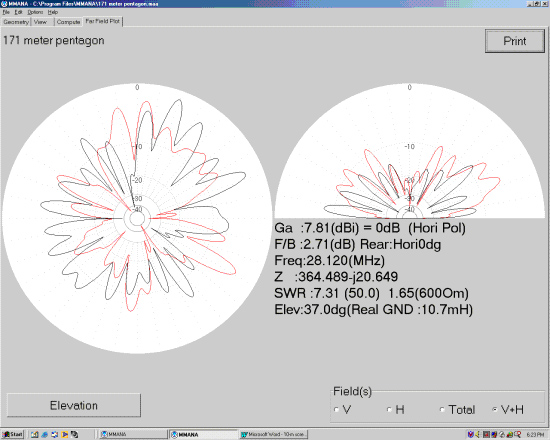
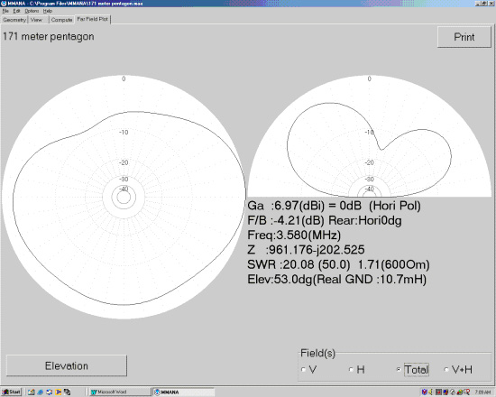
For the geometry defined by the location of our trees, we arrived at an optimum total length of 562 feet consisting of five segments of 167, 95.5, 114, 112 and 73.5 feet. The gain, angle of maximum radiation, calculated SWR and actual SWR of the loop for the important PSK-31 frequencies are summarized in the table.

Frequency (MHz) Gain (dBi) Angle ofMaximum Radiation (deg) Calculated  SWR ActualSWR
3.58 7.0 53 20.0 5.0
7.07 10.6 35 9.1 3.1
10.14 5.0 73 33.0 3.1
14.07 12.4 14 10.5 3.0
18.10 11.2 11 24.5 4.0
21.07 9.2 30 32.3 3.1
28.12 7.8 37 7.3 3.0

It’s important to remember that all antenna models are simulations; they are not the real thing. Simulators are a great way to learn to fly an airplane. But you can’t actually fly from New York to Paris in a simulator. It’s the same with antenna simulations. You’ll learn a lot about the antenna’s anticipated performance, but you can’t actually have a QSO. They’re the “next best thing to being there” and can be a lot of fun especially when the sunspots aren’t cooperating. More about the antenna’s actual performance later…

Hanging the 171 meter loop

The antenna is made of insulated number 14 stranded wire from the local home products outlet. Do not assume that these nominally 500-foot rolls of wire will contain 500 feet! Ours was 18 feet short. The wire is threaded through five “dogbone” insulators connected to the support ropes with 24-inch 125-lb test bungee cords. The support ropes are polypropylene agricultural hay baler twine. This rope is UV stabilized, has 240-lb knot strength and is available from farm stores for about twenty dollars per 6500-ft roll. The only limitation is its low abrasion resistance. Make certain the rope is not pulled back and forth over a tree limb in the wind.

Support ropes were put in place using a slingshot and spin casting rod and reel. A lead sinker, painted orange for visibility, was attached to regular nylon fishing line and launched over the appropriate tree limbs. The sinker was removed and the nylon line was used to pull mason’s twine back to the launch point. Finally the mason’s twine was used to pull up the baler twine. Don’t attempt to skip the mason’s twine step. Fishing line is not strong enough to pull up the heavier baler twine.

Manhandling almost 600 feet of wire is a tad more challenging than dealing with a 40-meter half-wave dipole. To measure it, we pounded two stakes in the ground exactly 100 feet apart and then walked sections of wire past the stakes marking the sections at the 100-foot intervals with masking tape. The completed loop with attached coax was laid out on the ground. The five insulators were threaded on and put into position. Bungee cords were attached between the insulators and the support ropes, which were raised incrementally into the trees. The entire procedure took the better part of a day.

Several accounts of full-wave loop antennas state roughly, ” It was the greatest antenna I ever had until it fell down for the umpteenth time and I got tired of fixing it.” After two initial breaks due to wear against the tree limbs, our antenna has successfully survived a rather brutal winter and spring here in eastern Ohio. Anticipating breaks, we first put in place permanent “lifting” loops of baler twine reaching from the ground to the support limbs. These loops are used only to raise the actual antenna support ropes. Not being under tension, the lifting loops never wear out and you never need to get out the slingshot again if the support ropes break. Having five support trees rather than four facilitates repairs since more of the antenna remains airborne when a support rope does break. In addition, the probability of all of the trees pulling against each other in a storm and tearing the ropes or wire decreases as their number goes up. Keeping the antenna completely free floating in the insulators also minimizes breaks. The wire can re-establish equilibrium when stressed in a storm. This can shift the point where the transmission line is attached, but with no detectable effect on performance.

The proof is in the PSK-ing

As shown in the table, actual SWR, as measured by both our ICOM IC-718’s internal meter and an auxiliary meter, are significantly lower than predicted by the model. At 20-30 watts output, the transceiver shows no sign of reducing power. Our expectation of needing to use a tuner with the antenna was pleasantly eliminated. On the other hand, the predicted high gain and low radiation angles are supported by our operating results.

Loops are known to be great for receiving and this one’s no different. Compared with our other PSK-31 antenna, a 20-meter dipole sized for 14.07 MHz, reception with the loop is almost always at least one S unit better. Noise levels are very low. Short-wave broadcasters, Dominion Observatory Canada at 3.333 MHz and the 60 kHz time signals from WWV all come in well. Even CB transmissions from the truckers on the expressway five miles away come in loud and clear on the IC-718. Some day we’ll have to buy a CB radio and see if we can talk back. Just kidding!

The antenna is great for receiving and “if you can hear `em you can work `em”. PSK-31 stations in Europe,South America, Japan and Africa have been worked regularly. Contacts have been made 80, 40, 30, 20, 17, 15 and 10 meters. Not requiring a tuner makes band switching a breeze. In the MMANA screen prints, the calculated directional patterns have an egg-dropped-on-the-floor look, but are in reality omni-directional. It’s noteworthy that the average height of the antenna is only 35 feet. An 80-meter dipole at this height would radiate most of its energy straight up, but this antenna’s angle of maximum radiation is a DX-friendly 53 degrees at 80 meters.

The simulations suggest that a better impedance match could be achieved on some bands by feeding the antenna with 300-ohm twin-lead or by using a 4:1 balun with the 50-ohm coax, but at the power outputs we’re interested in that’s really not necessary. The lengths of the individual segments could be optimized to favour a specific band of interest. We certainly plan to do some tweaking, but for us this may just be the perfect PSK-31 antenna – for less than fifty bucks and with a lifetime supply of baler twine left over. 

Back to top^
 

Why Vertical Antennas? – 6Y2A Contest Team

Why Vertical Antennas?

The selection of using vertical antennas was not a natural choice. The “conventional wisdom” for contest-expeditions and Dxpeditions was to use Yagi antennas when ever possible, regardless of the height. “Conventional wisdom” would tell you that a 3 ele Yagi at 25′ to 30′ high on 10m, 15m, or 20m would be the correct (if not only) choice.

When first researching our antenna selection, most of the major contesters in the USA said that the Caribbean stations ALWAYS came in at a high angle. Again, more “conventional wisdom” indicating that a low Yagi would be the best choice from Jamaica.

When we were running our propagation programs, the team noticed that the take off angle to the USA was actually a 1-hop LOW angle. Not the high angle that most people indicated. Which was right: conventional wisdom or the computer models?

In our first trip to Jamaica during the ARRL DX CW contest, the group used a blend of antennas:

  • Verticals for 40m -160m
  • Both a horizontal Yagi and vertical array for 20m
  • Yagis for 10m and 15m.

The use of Yagis on the high bands seemed appropriate, as we would elevate them between 0.5 and 1.0 wavelength high. The computer models indicated that the Yagi should perform OK.

While in Jamaica before the contest, the team ran extensive tests with the 20m 2 ele Yagi (45′ high) and the 2 ele parasitic vertical array. The results were astonishing: of the hundreds of tests, there were only a handful of times the horizontal Yagi was better than the vertical array (and only by a small margin).

Most of the time the vertical array was 2 S-units stronger than the horizontal Yagi! In fact, there were many occasions when a signal was an honest S-9 on the verticals (on the FT1000-MP) and S-0 and almost unreadable on the horizontal Yagi. This extreme difference can only be attributed to a signal arriving at a VERY low angle, where the Yagi had little gain.

These results, amidst many additional months of research, convinced the team that verticals by the ocean were the only logical choice for competitive contest-expeditions.

The following graphs were created by N6BV of the ARRL:

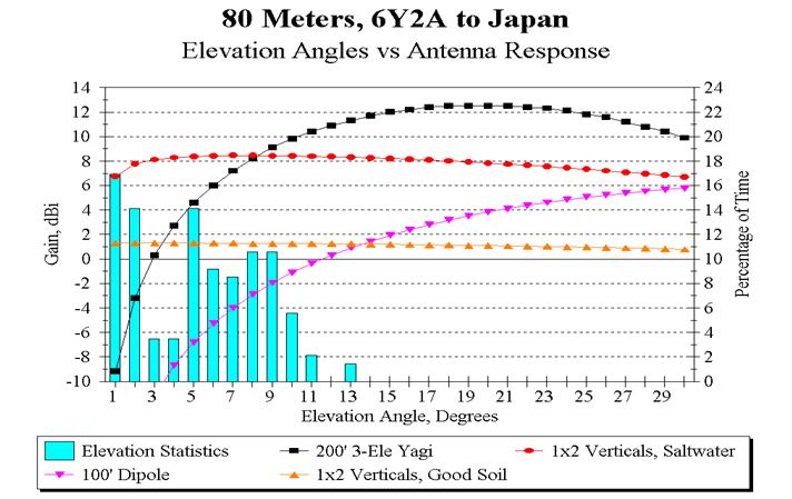
The first chart (below) shows an analysis of the take off angles from 6Y2A to Japan on 80m compared to various antenna choices.

First, let’s look at the vertical bars (light blue). This is a statistical grouping of all take off angles between 6Y2A and Japan over all times of the sunspot cycle, over all months of the year, and over all conditions. The data is displayed in the percentage of times a signal will arrive at a given angle: right X-axis is the % of time, and the Y-axis is the take off angle.

Thus by looking at the first bar on the left, we can see that on average, signals will be arriving at 1 degree take off angle nearly 17% of the time. In fact, you can see that ALL signals will arrive at or below 13 degrees on all occasions. Those are very low angles!!

Overlaid on the take off angles are the elevation-plane analysis of standard 80m antennas. Lets look at the 80m dipole at 100′ (pink with inverted triangles). By most standards, this is a very good antenna. But you can clearly see there is little gain at the low angles.

Next, look at the 1 x 2 verticals over good soil (2 ele parasitic vertical array). This antenna provides you with a large improvement over the dipole.

Now lets jump to the “ultimate” 80m antenna: a 3 element full size Yagi at 200′!! There aren’t many of those around, and who ever uses them will rule the band! (based on conventional wisdom). The 3 ele Yagi really does a great job over most arriving signals.

But let’s finally look at the 1 x 2 verticals over salt water (orange with circles). We can see that the verticals have a large advantage over the 80m Yagi at the very low angles. In this example, the verticals have a 16 dB improvement (3 S-units!) advantage over the Yagi. On the higher angles, the vertical still performs well. Overall, we believe the 2 ele vertical array over salt water is a better all around antenna than a full size 3 ele 80m Yagi at 200′!

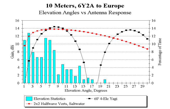
The next graph examines the take off angles on 10m to Europe. The reference antenna is a 4 element Yagi at 60′, an excellent contesting antenna. You can see that the 10m horizontal Yagi still does not cover the very low angles, and there is a null where there are still many signals arriving.

The comparison array is the 2 x 2 vertical array. The 2 x 2 verticals match the peak gain of the Yagi, but also offer excellent coverage over all arriving angles. Did we say that verticals by the beach rule!?

The team has done extensive modelling to all areas of the world on all bands, the results are typical of the examples above: Vertical arrays over salt water are very competitive antennas.

HF Multiband Antennas

MyTop Five
Backyard Multi-Band Wire HF Antennas by L. B.Cebik, W4RNL (SK)

My personal selection of the top 5 HF wire antennas for the backyard and for multi-band operation. Being a personal selection, there is no reason why your list should not be different from mine. But, along the way, I shall explain why I selected the 5 antenna types that I am including, giving you my views on both their advantages and their limitations. My list is simple and in no particular order.
1. The broadside doublet(s)
2. The dipole-doublet(s)
3. Fanned dipoles
4. The hohpl–horizontally oriented and polarized loop
5. The inverted-L
In order to make sense of what we say about each type of antenna, we need a point of reference. Since virtually all of the antennas will be horizontal, the logical baseline to use for comparisons is the resonant 1/2-wavelength dipole.So let’s review its characteristics.
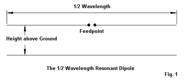
The 1/2-Wavelength Center-Fed Resonant Dipole The antenna that we loosely call the dipole is actually a 1/2-wavelength center-fed resonant or nearly resonant dipole. We usually construct it fromAWG #14 or #12 copper or copperweld wire for the lower HF bands, and we may use bare or insulated wire. Often, we mislabel multi-band doublets as dipoles because the antenna is about 1/2-wavelength at the lowest frequency of operation. But to be strictly correct, that antenna is a dipole only at the lowest frequency of use.

Fig.1 shows the two essential dimensions of a real dipole. Since we tend to feed the dipole with coaxial cable, we are concerned with the antenna length and resonance. In other words, we want a good match between the coax and the antenna feedpoint However, we also need to be equally if not more concerned with the antenna’s height above ground. The old adage, “The higher, the better,” arose from the use of wire antennas on the lower HF bands, where we generally could not achieve even a height of 1 wavelength.

Table 1.

Approximate Lengths of a Wave in Feet

Band     Frequency      Length                    Band        Frequency        Length
meters       MHz             feet                      meters         MHz                feet
160            1.8               546                         20             14.0                  70
80              3.6               273                         17              18.1                 54
75              3.9               252                         15              21.0                 47
60              5.37             183                         12              24.95               39.5
40              7.0               140.5                      10              28.2                 35
30              10.1              97.5
Table 1 serves as a reminder of how long a wavelength is on each of the HF amateur bands. For most backyard antennas, the average ham is lucky to achieve an antenna height of 1 wavelength on 10 meters, while the truly fortunate operator may get his wire to 1 wavelength on 17 or 20 meters. Every horizontal antenna is subject to essentially the same general phenomena that affect horizontal dipoles in terms of their height above ground. The lower the antenna as a fraction of a wavelength, the lower will be the overall gain and the higher the elevation angle of the radiation. Fig.2 illustrates the principle for a dipole placed at 1/4, 3/8, 1/2, and 1 wavelength above average ground. Unlike vertical monopoles, horizontal wires do not change their gain or elevation angle significantly with
changes in soil quality.
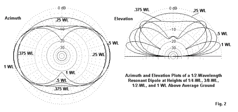
The elevation plots on the right show that the lower we place a dipole, the higher the angle of radiation, a fact that limits our effective range of communications under normal propagation conditions. The azimuth patterns on the left not only show the reduction of gain with a reduction in height, but as well the change in pattern shape. As we reduce the height of a dipole, its figure-8 shape at 1-wavelength devolves into a simple oval at a height of 1/4-wavelength. What applies to the dipole will generally but not without some exceptions, apply to any horizontal wire antenna relative to its height above ground at the frequency of operation. When it comes to height, think wavelengths, not feet! 1/2-wavelength resonant center-fed dipoles have many other interesting characteristics, but the ones that we have noted will guide us while we explore the top 5 multi-band backyard wire antennas. We shall also be setting aside our coaxial cable in favour of parallel feedline to an antenna tuner (ATU) or, as some British writers prefer, an antenna system tuning unit (ASTU). Consider the ATU to be a lifetime investment.

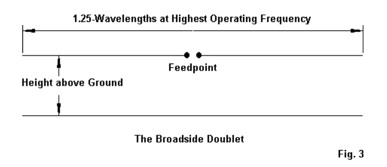
1. The Broadside Doublet(s): The broadside doublet is a simple multi-band doublet with a 4:1 frequency range for the desired characteristic. Fig. 3 shows the general outline.
In principle, the doublet is physically no different from a dipole. However, electrically, it is
significantly different. First, we feed it with parallel transmission line to an antenna tuner, because the feed point impedance varies greatly as we change operating frequencies from one band to the next. Second, we select the length so that the antenna will show a bi-directional pattern broadside to the wire on all of the bands included. Note that the length makes the antenna an extended double Zepp at the highest frequency. With an antenna tuner, the antenna will operate above its highest included frequency, but the pattern will breakup into multiple lobes. Table 2 provides the most convenient lengths and the bands included.

Table 2. Broadside Doublet Lengths and Amateur Band Coverage
Length (feet)         Bands covered
44′               10, 12, 15, 17, 20, 30, 40 meters
66′               15, 17, 20, 30, 40, 60 meters
88′                20, 30, 40, 60, 80 meters
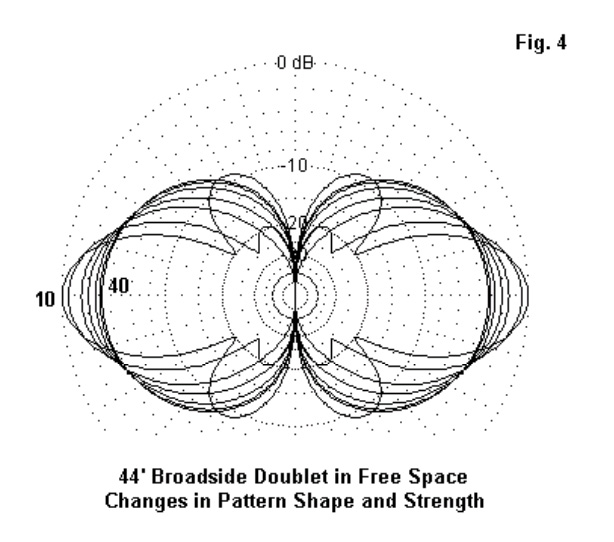
The chief advantage of the broadside doublet is that you always know the directions of your radiation or your most sensitive reception. A second advantage is the antenna’s simplicity for a 4:1 frequency range with the bi-directional characteristic. A third advantage, which we shall note shortly, is the flexibility of the antenna in forming wire arrays having different characteristics. With every set of advantages come one or more disadvantages. First, the antenna requires a wide-range ATU, since the impedance varies greatly from band to band.Since the exact values that will appear at the tuner terminals will vary with both the antenna height and the length and characteristic impedance of the parallel transmission line, I shall not provide specific numbers. Second, the gain goes down with frequency. The broadside doublet has its highest gain at the highest frequency. The gain drops a bit with each move to a lower band, while the pattern broadens. Fig. 4 shows the patterns overlapped in free-space models. However, remember that as we go down in frequency, the antenna will have a height that is a smaller fraction o fa wavelength. Hence–like the dipole–we can expect a further reduction in gain and a more significant increase in the elevation angle of maximum radiation. Hence,the higher you can place the antenna, he better will be its performance.
Part of the flexibility of the broadside doublet stems from the ease of covering the full horizon by adding only one more support. See Fig. 5.
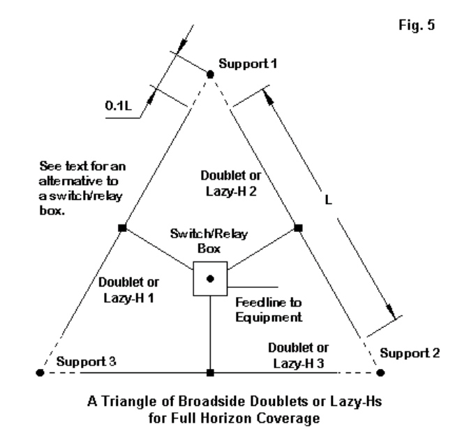
We can easily form a triangle of doublets. The triangle need not be perfect, so you can adjust it to aim more exactly at your favourite communications targets. With only a bit of end space(about 10% of the wire length), the inert wires will not materially affect the operation of the one in use. The only caution that you need to observe is to keep the feedline lengths identical. This caution applies whether you use a fancy switching box at the center of the array or whether you bring three separate and well-spaced lines to the shack entry point and do your switching indoors. Equal line lengths will mean that you do not have to do major retuning when switching from one antenna to the other. Hence, you can easily determine the most effective antenna for an incoming signal just by switching through the 3 antennas. Note that the triangle refers to either doublets or lazy-H antennas. That is part of the flexibility of the broadside doublet system. We can make lazy-H arrays using any of the listed element lengths and cover the same set of bands–but with more gain. Fig. 6 the outlines of a lazy-H.
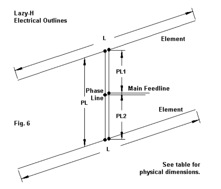
The lazy-H is simply 2 broadside doublets fed in phase. We need the center main feed point to ensure that the lines to both wires are the same length and therefore give us the same current magnitude and phase angle at both element feed points. So PL1 and PL2 are 1/2 of PL. The total length of the phase line assembly can be longer than the spacing, but for most installations, they are the same. The ideal spacing is 1/2 of L, the element length. Hence, the spacing is 5/8-wavelength at the frequency where the element is 1.25 wavelengths. This spacing provides maximum gain. You can reduce the spacing somewhat,but every reduction reduces the gain on all bands. The ideal lazy-H will net you almost 3-dB gain on the highest bands. There will be a slight reduction for the lowest bands, since the spacing will no longer be optimal. As well, the lower wire gets closer to the ground as a fraction ofa wavelength when we reduce the frequency.
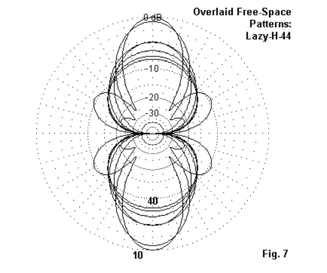
Fig.7 shows the overlaid free-space patterns to give you a basic idea of what happens to shape and strength,but remember to modify your expectations depending upon the height that you place the antenna. Getting the lowest wire at least 1/2-wavelength above ground is best,although lower heights for that wire will work. However, if that wire will be under 1/4-wavelength above ground, you maybe better off with a simple broadside doublet at the upper level. It will give you a lower radiation angle than the pair of wires. As a side note, in any set of in-phase fed antennas–whether doublets, Yagis, or whatever–the effective height of the combination will be a point about 2/3 the distance between the lowest and the highest antennas. Of course, we can make a triangle of lazy-Hs, just as we can for the basic doublet. There is a second multi-band array that we can make from the broadside doublet: an 8JK.
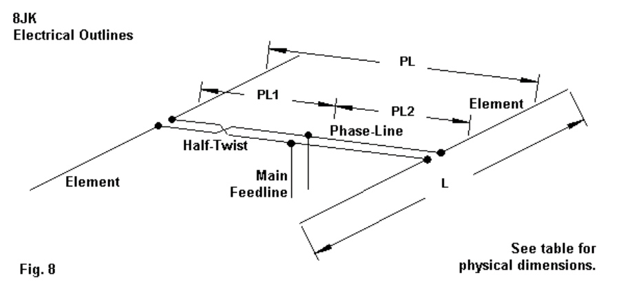
See Fig. 8 for the outline. Developed by John Kraus, W8JK, in the1930s, the antenna has undergone many variations. The versions shown here is designed for a 3:1 frequency range. It uses the broadside doublet lengths for the highest frequency,along with a total phase-line length that is 1/2 of the element length, L. However, note that when we create this end-fire array, we give one (and only one) of the phase line sections a half twist. The specific dimensions we have chosen from W8JK’s work are ones that give us an interesting pattern of gain, as shown in the free-space patterns of Fig. 9. The free-space gains are about equal on all bands. Indeed, the only factor that limits our frequency coverage is a very low impedance below the listed frequency limit.
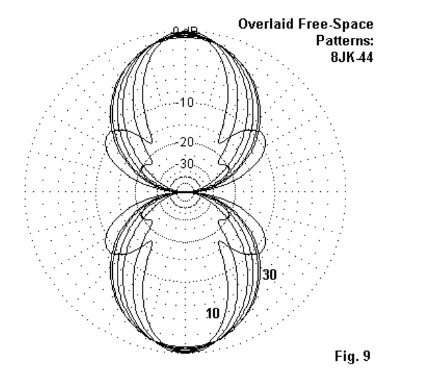
Of course, over ground, the gain will decrease as we lower the frequency,since the array will be lower as a fraction of a wavelength. Within the included bands, the gain will be much more equal from band to band than with the lazy-H. However, the peak gain will not be as high at the highest covered bands.

We may summarize the array dimensions in a simple table(Table 3). Remember that since we are using parallel feedline and an antenna tuner, broadside doublet lengths are not finicky. However, in the arrays, strive for equal lengths for each element.

Table 3. Lazy-H and 8JK Dimensions
Element Length       Phase-Line            Bands covered (meters)
(L, feet)            Length (PL, feet)             Lazy-H                8JK
44′                          22′                          10 – 40              10 – 30
66′                          33′                          15 – 60              15 – 40
88′                          44′                           20 – 80             20 – 60

2. The Dipole-Doublet(s): The dipole-doublets differ from the broadside doublets in two respects. First, rather than determining their length based on the highest frequency of use, we determine it based on the lowest frequency.In most cases, the doublet is a 1/2-wavelength dipole (approximately) at the lowest frequency. (Even the G5RV doublet is a dipole on 60 meters.) Again,since we shall use parallel feed line and an ATU, we do not have to be finicky in setting the exact length. Second, we do not give any preliminary thought to the lobe structure of the radiation pattern when we set up a dipole-doublet. Usually, we know that thepattern is bi-directional at the lowest frequency. However, we often do not think about the pattern above that frequency. As we shall see, the bi-directional patterns holds true until the antenna length as measured in wavelengths is greater than about 1.25.However, for many users, the patterns for the higher bands are mysterious. To get us started, Fig. 10 outlines the basic dipole-doublet. It chief advantages are simplicity and the ability to cover all of the HF bands above the frequency for which the wire is a 1/2-wavelength dipole. Hence, the preferred lengths are usually about 260′ for 160-meter coverage, 135′ for 80-meter coverage, and 67′ for coverage down to 40 meters. As noted, the G5RV 102′ doublet manages to be a dipole at 60 meters. The 67′ length will load on 60 meters, and the G5RV will load on 80 meters. In each case, the wire is about 1/3-wavelength,close to the limit for a center-fed wire.Below that length, the resistive part of the impedance goes too low and the capacitive reactance goes too high for most parallel line and tuner combinations to handle.
To start the process of becoming familiar with the typical patterns of a dipole doublet, examine Fig. 11. The dipole-doublet’s length in feet matters less than how long the doublet is at a given operating frequency in terms of half-wavelengths. When the length is close to an even number of half-wavelengths, we have as many lobes as we do half-wavelengths. The strongest lobe moves farther from a broadside direction as we increase frequency. As well, the beam width of the strongest lobe becomes narrower. Because the ham-band operating frequencies do not result in exact multiples of a half-wavelength, the lobe strengths will vary. But the count remains true.

If we operate the same antenna at odd multiples ofa half-wavelength, we obtain patterns composed of both emerging lobes and diminishing lobes. So the number of lobes is the sum of the old even number of half-wavelengths and the new even number of half wavelengths. In other words, we have twice the number of lobes as we do the length in half wavelengths. See Fig. 12. Again, because the nearest ham-band frequencies are not precisely the number of half-wavelengths listed, we find some of the lobes weaker than others. However, the count remains true.

The patterns would change if we used a 102’or a 67′ doublet when referenced to specific frequencies. However, relative to the frequency at which the doublet is 1/2-wavelength long, the patterns would re-emerge as shown as the antenna approaches lengths of 1 wavelength, 3/2 wavelengths, 2 wavelengths etc. In addition, the dipole-doublet is subject to the same rules relating antenna height as a fraction of a wavelength to radiation elevation angles that we discovered for the resonant dipole. If we understand the pattern development of a dipole-doublet, we can successfully use it without disappointments. The feed point impedance will vary over a wide range. In fact, it will be very high whenever the doublet is a multiple of a full wavelength. Hence, many users prefer 600-800-Ohm ladder line so that the line is an intermediate impedance between the highest and lowest values encountered. I like the old dipole-doublets for their simplicity and their long tradition of successful use. They are also flexible. We can set up a triangle of them, but the complex patterns may not give us the full horizon coverage of the triangle of broadside doublets. There is even an old (1930s) trick that we can use with the dipole-doublet: the center-support Y. Fig.13 shows the general outlines. The sketch shows 67′ legs, comparable to a 135′ doublet.However, you can use 50′ or 35′ legs with reduced low band coverage.
The Y-doublet’s special feature is the use ofa non-conductive center support (which may be no support at all if you can devise a way to hang the center freely). Either by spacing wires from a center pole or using triangular spacers, we bring down 3 wires, one from the inner end of each leg. The down-wires form the parallel transmission line. At the shack entry point, we set up a switching system to select the pair of wires to form the transmission line for the active doublet. In most cases, it will not matter whether thethird wire simply floats or is grounded:it is centred between the 2 active wires and has
almost no current on it. The Y-doublets form 120-degree angles. This angle makes almost no difference in the pattern relative to a linear doublet. There will be some differences in the patterns on the upper bands compared to those we saw for the linear doublet. Nevertheless, you will use an A-B-C switch to determine which pair of legs provides strongest signal. In order to make radical re-tuning unnecessary,itis important to
keep the transmission line wires equally spaced in a triangle all the way to the switch at the shack entry point. The Y-doublet is one way to overcome some of the limitations of the dipole- doublet’s multiple lobes on the upper HF bands.

3. Fanned Dipoles: For coax lovers, mythird selection for a multi-band antenna is fanned dipoles. I have seen a myriad of designs for these antennas, some of which include up to five or 6 bands and fold the longest elements into spaghetti. These designs I do not prefer, because they have very narrow operating bandwidths and erratic patterns due to combining long and short elements that both offer low feedpoint impedances. For reliable service with decent bandwidths, I prefer to construct my fanned dipoles a couple of bands at a time so that when one band shows a low impedance, the impedance of the other band is high. As well I prefer to widely space the shorter element outer ends from the longer element and obtain a wider operating bandwidth on both bands. In short, my preference in fanned dipoles is a 2-band antenna,although I would not rule out a 3-band combination. Fig. 14 shows the general outlines with the critical dimensions noted. Ordinarily, we support the outer ends of the longer dipole and suspend the shorter dipole beneath.

Let’s get a handle on the properties of fanned dipoles with a simple 80-40-meter combination. We shall look at two versions of the same antenna. One will droop the 40-meter dipole 10′ below the 80-meter dipole. The other design will place the 40-meter outer ends 1′ below the low-band dipole. The 80-meter dipole is set for 3.6 MHz, while the 40-meter dipole is set for 7.1 MHz. Table 4 gives us the dimensions and the performance of the array on each band with the 80-meter dipole 50′ above average ground.

Table 4.

Fanned 80-40-Meter Dipole Dimensions and Modelled Performance at 50′
Frequency     Length          Gain                   TO Angle                 Feedpoint Z
MHz                 feet             dBi                     degrees                  R+/-jX Ohms
Wide-Spaced Version
3.6                130.4            6.63                     86                              61 – j 1
7.1                  67.0            4.82                     44                              54 – j 0
Close-Spaced Version
3.6                 130.4            6.80                     88                               61 + j 2
7.1                   75.3            4.85                     40                               58 + j 2
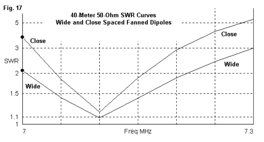
Although there is no significant difference in performance at the two design frequencies between . the wide and the close dipoles, we certainly can see a difference in the length of the 40-meter dipole. The wide-spaced version shows a length that approximates the length of an independent 40-meter dipole. However, the close-spaced version requires a much longer 40-meter element. Remember that the close spacing is still 1′, which is wider than some published and commercial designs.
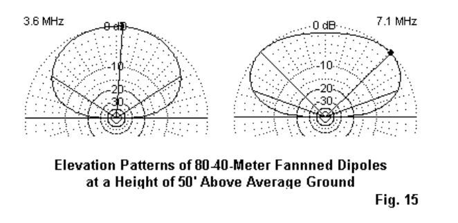
Fig. 15 shows the elevation patterns for the two bands. Like all horizontal antennas at low heights, neither pattern is ideal. The antenna on 80 meters is below 0.2 wavelength, and it only achieves 0.36 wavelength on 40 meters. As with all of the horizontal wire antennas, it could benefit from additional height.

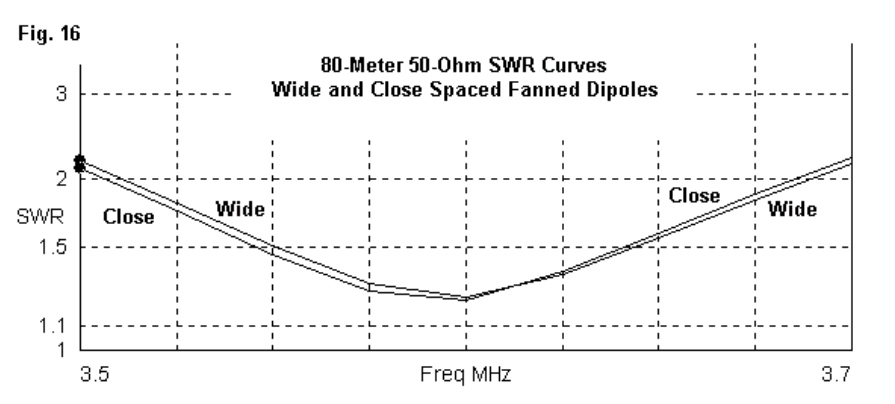
We cannot see much difference in performance between the two versions of the antenna on the design frequencies, but we did note the 40-meter dimension change to obtain that performance. The 80-meter length did not change as we altered the spacing of the 40-meter ends from the 80-meter wire. Obviously, in a fanned dipole arrangement, we expect the shorter wire to undergo more change than the longer one. The question is how we can sample the long-wire stability and the short-wire variability.

One way to see the difference is to examine the 50-Ohm SWR curves for the two versions of fanned dipoles. Since the 80-meter wire remained stable, we would expect the SWR (as a measure of changes in resistance and reactance also to remain stable. Fig. 16 tells the story.
The 40-meter 50-Ohm curves stands in stark contrast, as revealed by Fig. 17. The wide-spaced version of the antenna covers over 2/3 of the band. The close-spaced version barely handles 100 kHz. While the narrower bandwidth may be satisfactory for some operational needs, it also indicates that pruning the close-spaced 40-meter dipole to length is likely to be a somewhat ticklish task.
To understand why closing the space between the dipoles shrinks the usable passband of the higher-frequency dipole, we should make at least one more probe into the operation of the antennas. Modelling software gives us a look at the current distribution along the dipoles. Let’s compare the currents on both versions of the array.

Fig. 18 shows in the curves on the left the relative currents on the wires during 40-meter
operation. Notice that, despite the high impedance of the 80-meter dipole, there remains a low but significant current on the wire. Even with wide spacing and a predominance of current on the 40-meter wire, the two dipoles do not achieve the kind of independence that casual fanned-dipole theory suggests. When we move to the right and examine the closed spaced version ofthe array, we see a considerable increase of current on the 80-meter dipole. The closer that we space the two dipoles,the higher the current on the longer one. The higher the current that we find on the longer dipole, the narrower will be the operating passband of the shorter dipole and the more painful will be the job of setting its proper
length. As well, we are likely to find that a set of lengths that is right for one antenna height is not right for a different height. Fanned dipoles have served me well over the years, but only when I restricted the number of bands covered and when I separated the shorter dipole ends as far as feasible from the longer wire. As well, a 2:1 frequency ratio has tended to yield the most successful antennas with the widest operating bandwidth. Still, do not count the fanned dipole out when it comes to flexibility. I once tied a 10-meter vertical dipole to a horizontal 15-meter dipole with good success. One might even use close spacing (and patient pruning) to set up a combination for 12 and 17 meters or for 17 and 30 meters, where operating bandwidth is less of a question. However, I likely would steer away from combinations like 40 and 15 meters or 30 and 12 meters.

4. The HOHPL–Horizontally Oriented and Polarized Loop: The horizontal loop is subject to several misconceptions. Two of the most popular are that 1. The longer I make the loop, the more gain I get, and 2. The loop gives me omni-directional coverage on all of the HF bands. Basically, if you want more gain, then place the antenna higher. Moreover, even if you create a perfect circle, your pattern will not be circular on almost any band. Nevertheless, the loop is a good multi-band antenna easily fed with parallel transmission line and an ATU.
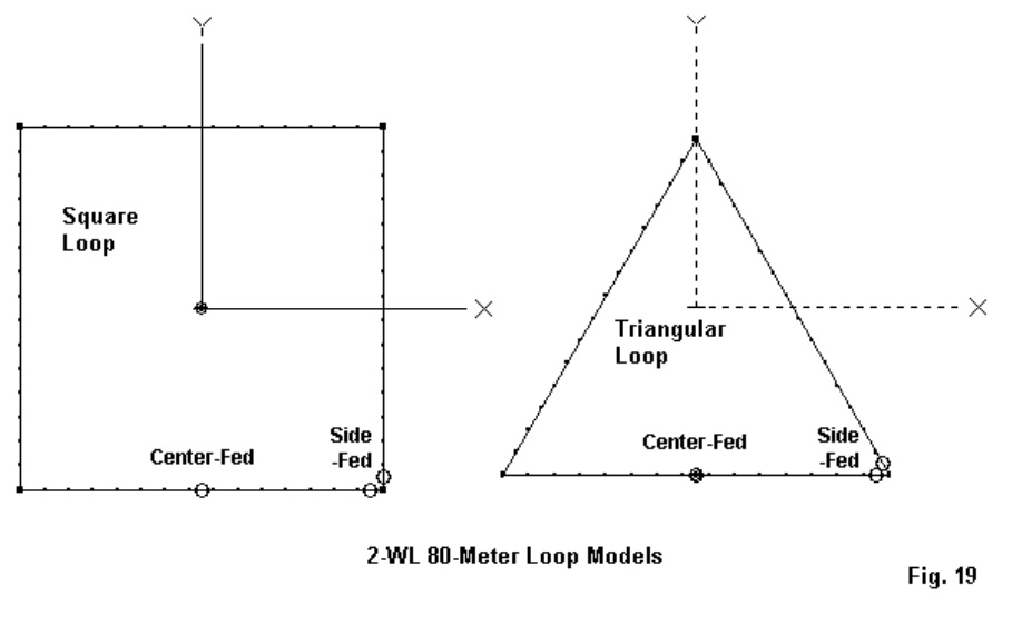
Fig. 19 shows the outlines of the two most popular shapes for a horizontal loop: the square and the triangle.Almost any other closed shape–regular or irregular–is possible. Most polygons with more sides tend to act like squares, so the contrast between the square and the triangle become good guides on what to expect from a loop strung along the perimeter trees in an average yard.Each loop shows 2 (different) feedpoints: a mid-side location and a corner location. These two points tend to coincide with the most convenient installation points from whichto runthe parallel feedline fromthe antenna to the
ATU. You can select an alternative position and nothing evil will happen. However, the patterns will not be as regular as the ones that we shall use for demonstration purposes.
I prefer to use a 2-wavelength loop at the lowest frequency ofoperation. In fact, our
demonstration loops will be 560′ loops with 80 meters as the lowest band. Loops have a peculiarity.

If we make them about 0.75-wavelength or smaller, they tend to radiate off the loop edge. If we make them close to 2 wavelengths or larger, they also tend to radiate off the edge. However,if we make the loop 1-wavelength–or thereabouts–at the frequency of operation, then it radiates broadside to the loop. Hence, a horizontal 1-wavelength loop becomes a good NVIS antenna, as our 80-meter 2-wavelength loop would become on 160 meters. Incidentally, we shall place the demonstration loop 70’above ground simply for the exercise.70′ is about 1/4-wavelength on 80 meters but 2 wavelengths on 10 meters. The phenomena of changing planes of radiation as we enlarge a loop will explain why my list of
the top five multi-band antennas does not include any vertically oriented loops. Lets start with a 1-wavelength loop.It does fine on the band for which it is cut. However, by the time we double the frequency of operation,the loop is radiating off the edge, producing mostly high-angle radiation. Such loops will make contacts, but not as well as a horizontal loop.
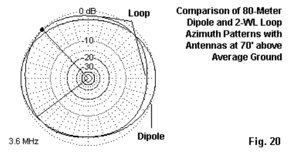
On the lowest band of operations, we do not choose the loop for gain. As shown in Fig. 20, there is very little gain difference between the loop and a resonant dipole at the same height. The mid-side-fed square loop used to generate the loop part of the pattern is not even significantly more omni-directional than the dipole pattern. However, at their lowest operating frequencies, loops tend to show a lower radiation angle than a low dipole. In the case that uses antennas at the 70′ level, the dipole’s take-off angle is 58 degrees, but the loop’s angle is between 44 and 50 degrees, depending upon the loop shape and the feed point position. This advantage is useful at the lowest operating frequency, but it does not last as we increase frequency. By the time we double the operating frequency,the take-off angle for loops tracks well with the take-off angles for doublets at the same height.
Loop antenna shape and the position of the feedpoint do make a difference to the antenna’s pattern and performance.

Fig. 21 shows the 3.6-MHz azimuth patterns for the two loops (square and triangular) with both corner and mid-side feed points. The notation FP on the plots shows the relative position of the feed point to the development of the plot. The triangular plots are–relative to the feed point position–more alike than the two plots for the square loop. In both triangle cases, the direction of the main lobe crosses the feed point and a point in the middle of the opposite side. The main difference is a reverse in the slight gain advantage. For the corner-fed triangle, maximum gain is away from the feed point, while in the mid-side version, gain is more toward the feed point. The squares, however, show a more distinct pattern difference, depending upon the feedpoint position. The corner feedpoint produces a nearly circular pattern, while the mid-side feedpoint yields a 4-lobe pattern. Although there are no major differences in gain, Table 5 presents the modelled maximum gain values and take-off angles for the 4 loops on various HF bands, using our basic 560’loops at 70′ above average ground. Because we shall use an ATU, the feedpoint impedance data is not especially useful here.
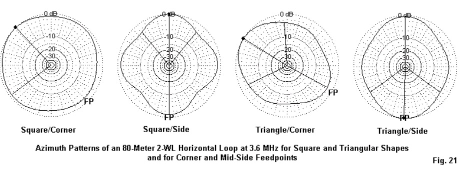
Table 5. Modelled Performance of 560′ Horizontal Loops at 70′ on Selected Amateur Bands

Note: Performance shown as Maximum Gain (dBi)/TO Angle (degrees).
Loop           Square             Square             Triangle              Triangle
Frequency   Corner-Fed        Side-Fed         Corner-Fed         Side-Fed
3.6              5.9/50               6.7/44                7.1/48              6.4/45
7.0             10.6/27              9.9/26                9.7/28             10.4/28
14.0            12.9/12            11.6/12              13.9/13             11.2/13
21.0           14.6/9              14.3/9                13.4/9               12.4/9
28.0            15.1/7              13.6/7                14.1/7                11.0/7
I have inserted Fig. 22 immediately following the chart of modelled gain values so that you will not make too hasty a decision on which loop to select. It shows the patterns on 40 through 10 meters that produce the gain figures in the chart, at least for the square loops. Above 40 meters, we discover patterns with many lobes. The higher we go in frequency,the more lobes we encounter and the more variable we find the lobe strength. As a general rule of thumb with simple wire antennas, the higher the gain of a lobe, the narrower its beam width. So we obtain maximum gain only over as mall target communications arc. In these patterns, dots serve to locate the feed point position on the loop relative to the pattern.

Fig. 23 provides the corresponding patterns for the triangular loop. On 80 through 20 meters, the loop produces patterns that have a distinct axis on the line formed by the feedpoint and the opposing loop position. Above 20 meters, the patterns become as individual as snowflakes, each very regular but distinct from the other patterns. When we combine the patterns of the three plot figures together, we may finally come to understand that on the upper HF bands, horizontal loops do not produce patterns that are more omni-directional than doublets. The patterns are simply different in the relative positions o the lobes and nulls. As well, the chart shows that on the upper HF bands, the radiation angles are similar to those of simple wire doublets.

So why choose a horizontal loop as one’s multi-bandwire antenna? One good reason is the improvement in radiation angle on the lowest frequencies of operation. A second good reason is because you have the perimeter supports already growing in your yard.A third reason is because closed loops tend to be less prone to the build up of static charge relative to doublets with un-terminated ends. This feature does not guarantee immunity from all noise sources. Nor does it guarantee immunity from the hazards or lightning and associated thunder storm dangers. A fourth reason is becauselarge closed loops tend tohave less high-angle radiation. What may be more important, this fact means less receiving sensitivity to high-angle sensitivity to QRM andQRN from closer-in sources. Fig. 24 compares the 21-MHz elevation patterns for a simple 135′ linear doublet and a 560′ triangular loop with its feedpoint in the middle of oneside. Although the exact shapes of the
15-meter elevation patterns will vary from one loop to another in the set that we have been examining, they all share the general property of having less high-angle radiation. The loop has several advantages that recommend it as a multi-band antenna,if you can live with the upper band patterns, if you have room for the array, if you can find the wire and the supports, and if you are prepared for the maintenance that a long stretch of wire requires. All those “ifs,” of course, represent the disadvantages of the horizontal loop.

5. The Inverted-L: In principle,the inverted-L is any antenna that physically looks like a tipped-over letter L. Electrically, it includes not only tuned systems with radials, but as well, any sloping wire that runs from an antenna tuner at ground level to some higher end-point. (A sloping wire has essentially the same vertical and horizontal radiation components as the more formally positioned L.) What we used to call a random length, end-fed wire belongs in this group as much as the 160-meter inverted-L with 64 radials at its base. In more practical terms, the average backyard antenna builder is unlikely to lay down a major radial field for the most efficient 160-meter operation. The portion of the antenna above ground is no problem, since it involves running a wire up as high as available supports will permit and then running the remainder horizontally. The radials are the major hindrance to using the inverted-L. So let’s reduce the radial field to a mere 4 radials, each 1/4-wavelength long at 160 meters, that is, about 135′. With this reduced field,let’s assume that we have 50′ of vertical support. Then an all-band inverted-L will look something like the left-hand portion of Fig. 25,
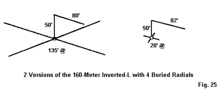
To achieve resonance on about 1.85 MHz with AWG #12 wire throughout, we need an 80′
horizontal run. Incidentally,in my model, the radials are buried 6″ deep in the ground, but the exact burial depth is not critical.Now let’s add a second dose of reality. Many hams have backyard filled with gardens, children’s toys, garages, etc. Hence, we find an unwillingness to commit to more than short radials. So the right-hand side of Fig. 25 shows the same set-up with 4 20′ radials. The horizontal section of the antenna needed a 2′ extension to restore resonance at 1.85 MHz.Now let’s compare performance (Table 6).

Table 6. Inverted-L Performance with Full and Short Radial Systems
Antenna 135′ Radials 20′ Radials
Frequency     Gain       TO Angle         Feed Z        Gain      TO Angle       Feed Z
MHz            dBi    degrees R+/-jX   Ohms          dBi         degrees     R+/-jX Ohms
1.85 -2.2         29                38               – j 2           – 2.6             29              47 + j 2
3.6 3.5           84            4500+ j1750 3.8 84 5200- j150
7.0 4.0 35 700 + j 750 4.0 35 900 + j 800
14.0 5.2 22 300 + j 300 5.3 23 350 + j 350
21.0 6.0 13 200 + j 80 5.8 13 250 + j 200
28.0 7.7 10 200 – j 100 7.5 10 200 + j 30

In practical terms, we find a significant performance difference only on 160 meters. The #12 inverted-L is under ideal conditions about 2 dB less effective than a full size vertical monopole. When we shorten the radials, we lose another half-dB of gain. Otherwise, the two systems are roughly equivalent for all-band operation. The short radials and longer horizontal section of the smaller system do raise the impedance values, but if a tuner will handle one set,it will also handle the other. Fig. 26 shows the patterns for 160 meters, with the antenna orientation marked. Note that the horizontal section offsets the vertical monopole pattern away fromitself bya small amount. Also note that there is still significant current in the horizontal portion ofthe antenna. This shows up as the figure-8 horizontallypolarized component of the pattern that is about 10-dB down from the vertically polarized component. As we move above 160 meters, we can discover one reason why many inverted-L users think of the antenna as a good (even if not perfect) general communications antenna. Fig. 27 provides patterns for selected hambands, with the frequency and the TO angle noted for each azimuth plot. Relative to patterns for closed loops and linear doublets, the patterns are almost all more equally distributed around the horizon. As we increase frequency, the combination of increasingly strong horizontally polarized radiation and the remnant vertically polarized radiation tend to provide a modicum of gain in almost every direction. Only when we reach 10 meters do we find a pattern of well-defined lobes and nulls, but the nulls are not as deep as those we find with loops and linear doublets. The cost of the fuller coverage is lower maximum gain. There is no significant difference between the pattern shapes for the L with a full radial field or the L with short radials. Remember that these patterns apply to an inverted-L with a 50′ vertical section. If you bend the L at a lower height, the TO angles for 80 through 10 meters will rise, and the gain and exact pattern shape may change. However, let’s consider one more version in which the user does not lay down a symmetrical (or thereabouts) radial field. The one thing necessary to the use of the inverted-L is a good RF ground, so this user lays down 1 buried radial about 20′ long. See Fig. 28.
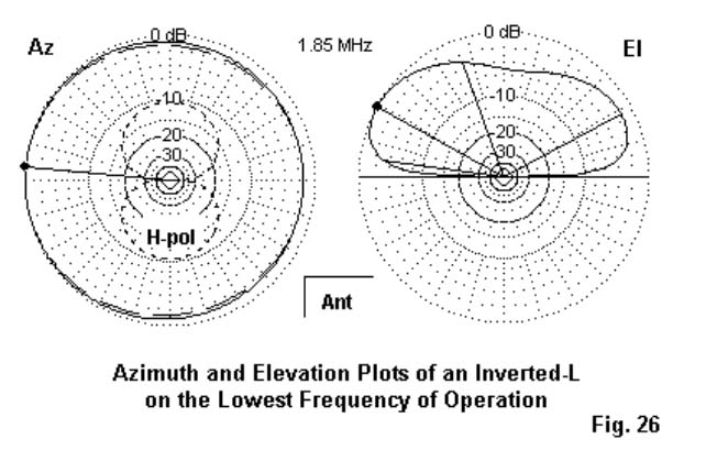
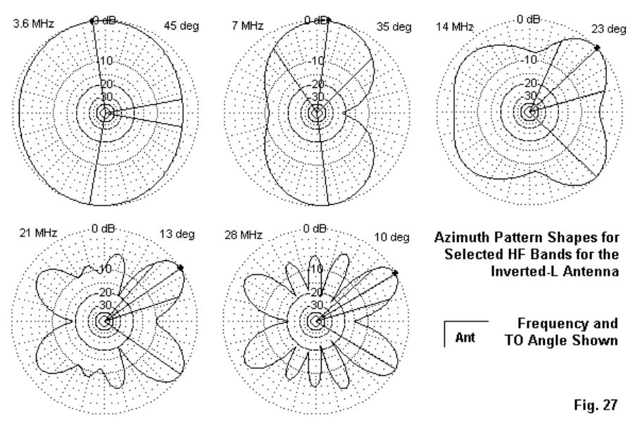
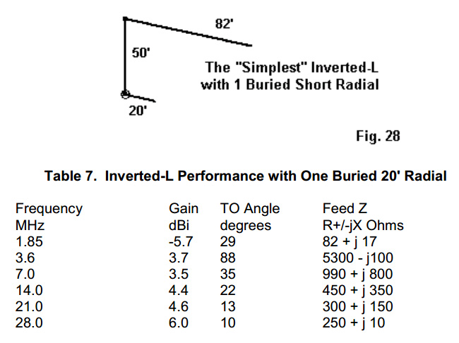
Table 7. Inverted-L Performance with One Buried 20′ Radial
Frequency Gain TO Angle Feed Z
MHz dBi degrees R+/-jX Ohms
1.85 -5.7 29 82 + j 17
3.6 3.7 88 5300- j100
7.0 3.5 35 990 + j 800
14.0 4.4 22 450 + j 350
21.0 4.6 13 300 + j 150
28.0 6.0 10 250 + j 10

As Table 7 shows, performance does diminish relative to the other systems. However, only on 160 meters, where we lose another 3 dB of gain, is the result unworkable. On the other bands, we obtain usable performance. For emergency and field operations, the 1-radial inverted-L may be usable from 80 through 10 meters. However, for home use, we should strive to add as many radials shaped however the ground will permit–as we can, even if weonly add one every few months. The usual safety precautions apply to radials: get thembelow ground where playing children, gardening spouses, and seeing-eyelawn mowers cannot reach them. If you usea tree to support the feed-end of the antenna, be
sure to space the vertical well away from the tree trunk. In addition, make sure that no one can touch the antenna or its feedpoint during operation.

You will note that the 80-meter impedance is very high, higher than most antenna tuners can handle.For this reason, many inverted-L users prefer to use wire lengths longer or shorter than the 130′ length that I used in this demonstration. A 3/8-wavelength inverted-L (about 100′ including both the vertical and horizontal sections) will move the very high impedance frequency to the 30-meter band. Pattern shapes will change, but the general properties of the inverted-L will remain: good (but not great) bulbous patterns for general communications in almost every direction. One final question: where do I place the antenna tuner? The answer is simple: at the antenna feedpoint. This position is standard in the field, where we usually terminate the antenna at the operating position with a manual antenna tuner. For this antenna, we actually need a single-ended network tuner. At home, the inverted-L is an ideal application for one of the weather protected automatic tuners (using precautionary additional weather shielding) with the case or ground lead connected to the radial side of the system.

The advantages of this type of system are obvious: automatic (or semi-automatic) tune-up with a coaxial cable from the antenna feedpoint to the rig. The disadvantages are the initial expense of the automatic tuner and periodic preventive maintenance. Final Notes: We have now surveyed my personal five favourite multi-band wire backyard antennas. There are others that I might have included. In fact, I thought of some others, but gradually discovered that they were mostly variations of the ones that I included. For example, there are some sloping and bent wire antennas calling for either measured or random-length “counterpoises.” However, they are simple variations on the inverted-L. Linear dipole-doublets have inverted-Vee variations. I have omitted antennas using traps, simply because traps require maintenance and represent an advanced project for most folks who roll their own.

All of the antennas I chose involve only wire and feedline plus, of course, the antenna tuner. For all but the inverted-L (and possible the fanned dipoles), we need a balanced tuner that will handle a very wide range of resistance and reactance at its terminals with the highest possible efficiency. Although there are a few balanced network and Z-match tuners available, most hams still use single-ended network tuners with a 4:1 balun at the terminals. Unfortunately, not all 4:1 tuner baluns are made equal, and many show high losses in the presence of either high reactance values or very low impedances that may occur as the feedpoint impedance is transformed along the parallel feedline. There is an alternative system for using the single-ended network tuner in the manner in which it is most efficient: as a single-ended network. Fig. 29 shows the essentials.
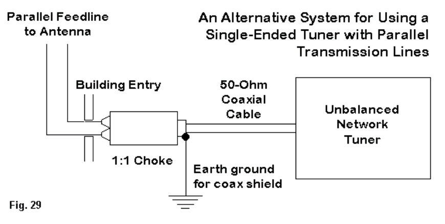
At the shack entry point, we terminate the parallel feedline with a 1:1 balun.Actually,the unit is a simple choke in preference to a transmission-line transformer that prefers a minimum of reactance. A W2DU type choke composed of about 50 ferrite beads around a length of coax tends to work quite well in this application. We run a lead to an earth ground from the coax braid right at the coax side of the choke itself. This measure tends to attenuate any remnant RF that might get onto equipment cases or into circuitry. Make the coax run as short as possible using the lowest-loss coax that you can obtain, since there will still be a considerable SWR on the line to the tuner. However, this line goes directly to the coax connector on the tuner output side for single-ended processing. The system is not perfect and does have small losses. However, in most cases, it tends to clear the shack of unwanted stray RF from indoor parallel feedlines, and it does allow the single-ended tuner to effect a reasonably efficient match with the remainder of the antenna system. This system is not new,being almost as old as the W2DU type choke itself. I first recommended it as one solution to problems some folks had back in 1980 with G5RV antenna systems.
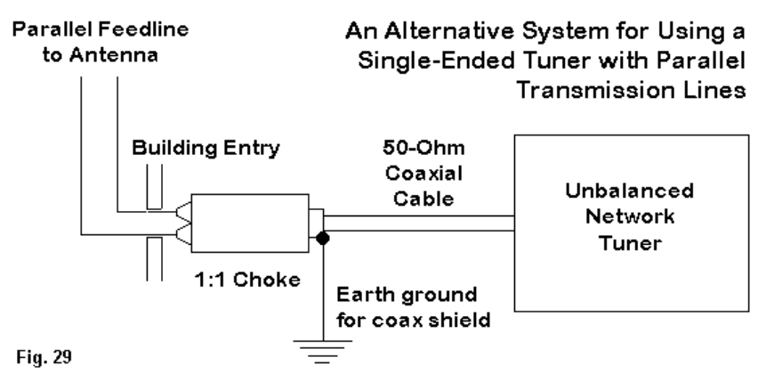
There is a vast territory that these notes have not covered. We can make multi-band beams, multi-band verticals, and a number of other antennas that will cover 2 or more of the ham bands. I encourage you to experiment with antennas, since wire is inexpensive and you can develop temporary mounts to put up and take down your trial antennas. But when you do erect an antenna, please be sure to give it that same care that you give your transceivers. Periodic preventive inspection and maintenance will ensure that the antenna gives you all the performance that it can every time you fire up the rig. Attention to safety will protect both property and the lives of those you love the most including  yourself.
As for those other possible antennas, there are always future FDIM celebrations to cover them.

73 L Cebik W4RNL

Troubleshooting Antenna Traps

TROUBLESHOOTING TRAPS

Below is a document that was produced by staff members at Cushcraft some years ago.. I have reproduced it here but it remains of course, copyright of Cushcraft Corporation… 

It refers mainly to the old 1/4 wavelength AV series of antennas (12AVQ, 14AVQ etc) hence the references to radials..  The “R” series (R5, R7 etc) are 1/2 wavelength antennas, and the radials are NOT 1/4 wavelength resonant..

If you fail to get a good VSWR on one band there are three possible problems. The first is that the trap is bad or mistuned. Another is that the radials are incorrectly measured or attached. The third is that the length of the radiator has changed, possibly becoming shorter because of a loose clamp allowing one section of tubing to slide into another section.  Check physical dimensions and connections first. Always troubleshoot a trap antenna problem working from the highest frequency to the lowest.. One way to test the radials is to attach temporarily one more quarter wavelength radial that is carefully cut to the correct length for the band on which the problem occurs.  Did the VSWR decrease? If so, then improve the radial system, if it did not, then there may be a trap problem.

A trap is a high Q parallel resonant circuit. If the antenna works on the next lower band, then the coil of the trap is good, and has good connections to the aluminium tubing. If the next lower frequency does not work then the coil may be open. The balance between inductance and capacitance Is critical, and requires good equipment to assure proper adjustment. Refer to the trap trouble-shooting section for checking individual traps.

SWR CHANGES WITH THE WEATHER

Ice or heavy sticky snow that sticks to the radiator and traps will cause the resonant frequency to shift lower, due to a fatter radiator. If your antenna is ground mounted and you have only a few radials then in wet weather ground conductivity may change and therefore VSWR will change as soil conductivity varies. Any cracked, torn or wrong size plastic caps on the top of traps will allow moisture in, affecting the resonant frequency. Putting any type of sealant on the top of the traps will likely detune them and create voltage breakdown problems since the top of the trap is a high voltage point.

VSWR CHANGES WITH POWER

If VSWR varies with power level on one or more band the problem may be in the VSWR bridge. There can be a non linear variation of diode action at different power settings. This is common with inexpensive bridges. It is possible to overload a diode in the forward power mode. The diode is now on a different slope of the curve in relation to the reflected power diode which is not overloaded. The end result is that your VSWR will apparently increase when you go from low to high power. Example: 1.1:1 at 50 watts , 1.4:1 at 800 watts. Observe VSWR as you slowly increase power. If VSWR slowly increases you may be over­loading your bridge. If you see a large jump in VSWR at a specific power level not related to a slow increase in power, you could have voltage breakdown troubles with your antenna

Causes: Poor, or Intermittent connection in the radial system. Poor connection in a trap. High voltage breakdown on a trap, (sniff the end cap to see if burned). High voltage breakdown in Input coaxial connector or matching network (if supplied).

VSWR too high on one or more bands.

Causes: Mistake in assembly. Poor, or no ground or radial system. Defective trap, See trap troubleshooting.

TRAP TROUBLESHOOTING 

On the AP-8 antenna check the connections at each trap.. Is the ground screw tight? Are the screws tight at each  strap  connecting  the  radiator  tubing  to  the capacitor tubing?  A poor connection at any  of these points will cause that trap to be detuned and result in poor VSWR on the band for which that trap was tuned. If you  have the AV-5 antenna check each  trap to insure that the cover is tightly secured.   The cover is the 1 5/8″ aluminium tubing over the coil, On top of the cover is a plastic cap. Any movement of the cover will cause intermittent VSWR conditions on the antenna. You   may  test for  a  loose  cover  easily   while   the antenna Is still assembled. Grasp each trap in your hand and apply a moderate amount of pressure in a clockwise and then  in  a counter clockwise  direction about the axis of the element. If the cover slips It will require tightening. A hex head screw Is at the base of the trap. Tighten this screw with an appropriate screw driver or spintite.  Be careful not to apply  so much force as to strip out the sheet metal screw. If the hole is already stripped, or gets stripped accidently, it is an easy matter to fix by substituting a #10 x 3/8″ or #10 x 1/2″ self tapping screw in the enlarged hole, If all your traps pass the mechanical test, and seem to be installed properly, then a frequency check is in order. The traps should be marked before removal so that proper re-assembly is assured. Remove all of the traps and bring them Indoors for inspection.   A list of Cushcraft traps and resonant frequencies are presented below, so that you can check to see if a trap is near the frequency to which it should be tuned. Use as little coupling as possible so that the dip oscillator Is not pulled in frequency. Use a frequency counter or receiver to determine the frequency of the dip oscillator. (Nowadays we can use our Antenna Analysers of course are sexier than a GDO..)

TRAP     OPER FREQ        OSC FREQ               OSC COUPLING

TF                   28.8                    27.87                            Capacitive

TG                   21.3                    20.17                             Capacitive

TH                   14.2                     12.92                            Capacitive

TJ                    7.20                      5.81                              Capacitive

TR                   21.3                    20.23                             Capacitive

TQ                   28.7                    26.8                                Inductive

24.65                 23.5                                Inductive

TS                   21.25                  20.1                                Inductive

18.11                  17.5                                Inductive

TT                    14.47                  13.49                              Inductive

TU                   10.19                    9.9                                  Inductive

TV                   7.3                        5.8                                   Capacitive

The method of coupling to the dip oscillator is important. Traps from the AV series of antennas require capacity coupling because the coil is shielded. Place a trap on an insulated surface (large cardboard box) and couple your dip oscillator meter (GDO) to the trap as shown below. Be careful to follow directions explicitly.

Capacitive Coupling

For capacitive coupling the tip of the GDO coll should be just slightly Inserted into the lower end of the aluminum tubing of the trap. Inductive coupling can be used where the coil is visable except for the TV  trap  where  the  dip  can  be  found   easier  by capacity  coupling. When checking dual  frequency traps   (TQ  & TS)  short the trap  not  under test to prevent obtaining a false reading. It should be noted that  the  dip   meter frequency   is   lower  than   the operational   frequency   of  a  trap.   This   is   caused because the trap will load the dip oscillator and lower it’s  frequency.  You should  use the listed  oscillator frequencies as a guide.   Temperature and   humidity can have a   +/-   100  KHz  effect  on   traps.   If the readings are within 100 KHz of the listed amounts, do not worry, the effect upon the assembled antenna will be minimal, Shorted turns or other serious defects will cause wide   shifts from the norm. One or two megahertz is a definite indication of a bad trap . All coils are sealed and are difficult to repair properly. When all traps are checked and corrected,  reinstall them   in   proper  order,   (as  you   previously   marked them)  and your multiband trapped vertical is now ready for action.

Inductive Coupling

Below is part of an email that I received from Dick W5TA which contains more “hands on” experience of fixing traps..

Getting ready for Field Day, I repaired an old  HyGain tribander which belonged to our local radio club. We found that the connections of the copper wires in the trap coils to the screws connecting them to the aluminium tubing had seriously corroded. With most traps there is one or more retaining screws.  After their removal you can pull off the end caps and pull the trap apart.  It’s an outer aluminium tube over a plastic inner rod serving as a coil form.  Often you will find bug nests, insect carcasses and corrosion bridging turns of the coil as well as corrosion at the terminals and maybe the whole coil.  If you rewind the coil, take care to first note the wire size and number of turns.  With this, clean up and reassemble and you have a “good as new” trap.

I have to recognize Kees Talen, K5BCQ, who showed me this procedure.

Very 73,
Dick  W5TA”


Balun Construction

Here are some details on how to construct a simple Balun. The first one changes your 50 Ohm Unbalanced output from your transmitter to match 200 ohms balanced to your balanced feeders antenna. It is not critical. The antenna may have 450 Ohm open wire ladder line. The output of the 50 ohm to 200 ohm balun will work just fine and so will your antenna.

The second balun is a simple 50 ohm unbalanced to 50 ohm balanced lines and is quite useful when the antenna has a low impedance unbalanced feeder feeding a length of coaxial line. The balun may be incorporated into the centre insulator of a dipole and will eliminate stray RF currents flowing back down the outside coaxial braid into your shack

A 50 ohm unbalanced to 200 ohm balanced balun and
A 50 ohm unbalanced to 50 ohm balanced balun

.

Two No. 14 wire gauge wires around an Amidon T63 Ferrite Core

Constructing a G5RV Antenna

G5RV Antenna Construction

Construction your own antenna is not all that difficult and certainly a lot less cost than buying one that will deteriorate the same way in the weather.

Here are some interesting facts about common antennas:

A 3el full sized perfectly matched yagi will give you about 6.5 db forward gain

A 2el full sized perfectly matched yagi will give you about 4.5 db forward gain

A 2 or 3El trapped Yagi will give you about 0.5 to 1.0 db gain less than a full sized equivalent.

A 2el full sized perfectly matched yagi with folded elements. (Hexbeam, Spider Beam, Moxon  and others of their ilk will give you about 4.0 db forward gain.

A perfectly matched resonant dipole will give you 0.0 db gain

A trapped dipole will give you a 0.5 to 1.0 db trap loss compared with standard dipole.

G5RV, OCF and other weird and wonderful antennas are a compromise to gain bands. You gain with wide frequency coverage but you lose dbs compared to a standard dipole.

A quarter wave vertical, perfectly matched with 128 radials will give you zero db gain

Reduce the radial numbers, insert traps, reduce the length with helical windings and you lose valuable db.

With antennas – you don’t get something for nothing. Yes, you will have contacts with any antenna. The more compromised the antenna is, the less contacts you will have with it.

The case of the commercial $195.00 G5RV wire antenna kit

Yes, it will work just fine. Not as well as a full sized dipole on any given band but it will work well. No marketers of these snake oil antennas have ever managed to get any gain out of them. They are less efficient than a full sized dipole. Simple fact. On the other hand they will allow you to make contacts on 80M, 40M and other bands.

Shell out $195 or build one?  They both work the same!!!!!!  If you scrounge around in junk sales or your mates you may find 105 feet of wire. Any wire, Plastic covered, bare wire even old transformer wire. But “It stretches” I hear you moan. Simply tie 60 or 70 feet around a trailer hitch and the other end to a tree and put slow tension on it. You now have hard drawn copper wire that won’t stretch. Old timers will know that trick!!!

Open wire feeders???? They don’t have to be expensive 450 ohm ladder line!!!!! Learn how to cut a bit of plastic to make insulators about 2 inches across. A small hole or slot in each end will allow you to thread the insulators onto the wires. Any wire will do. A local mate of mine uses #18 galvanized garden wire. A roll at Mitre 10 for 6 bux!!!!! You only need a 34 foot length of feedline.

Insulators??? One side of a plastic clothespeg. 16 clothepegs at the supermarket will set you back about 3 bucks. Any plastic will work. Currently, for all my insulators and antenna materials I go into the supermarket and buy a nylon chopping board. I then use a small jigsaw with a coarse blade and can cut out anything I need in a few minutes. I would strongly suggest that you don’t purloin your XYLs kitchen board in the heat of the moment or you will experience severe RF sparking and possibly meltdown.

“But it might not work” I hear you say. Get over it. Learn how to solder. Get hold of a mate in the your club to help. Build the bloody thing and get a mate with an antenna analyzer to put it on resonance and it will work just the same as a $195 one and you will learn a helluva lot about antenna and how to put them up. There are tons of books and lots of antenna information on the net. I just Googled G5RV antenna construction and I got 41,000 hits. The first ten gave me endless possibilities for construction.

Building an antenna is not rocket science guys. There is nothing magical about a store bought antenna.

Sorry … there are magical. They make your money disappear in a flash!!

73, Lee ZL2AL

80M Dipole Construction

The drawings below apply to all dipoles. Quality construction will mean that your dipole will perform properly and stay up for a very long time. Shoddy insulator and centre fastenings will mean that your antenna will be on the ground sooner or later and you will have to rebuild it all over again.

Construction Details

Insulator Details

Lead-In Options

The diameter of the antenna wire is not critical and the length will vary slightly from 0.7mm to 1.5mm If the antenna wire is covered with plastic insulation you will find that the length of the dipole at any calculated frequency will be about 4% shorter. The plastic covering seems to add to the inductance or capacitance and tends to make the antenna operate at a slightly lower frequency. Antennas cut to length will tend to be resonant at a lower frequency lower to the ground. When raised to maximum height the resonance will return to it’s design frequency.

73, Lee ZL2AL