Click on the following link:
The HyGain TH-3MK4 Triband Antenna In PDF Format
73, Lee ZL2AL
I ran across this a while ago in a post from the TCDXA (Twin City DX Association) The info could prove useful the next time you run across an “impossible to loosen” nut on a tower.
“Machinist’s Workshop” recently published information on various penetrating oils. The magazine reports they tested these products for “break out torque” on rusted nuts and bolts. A subjective test was made of popular penetrating oils, with the unit of merit being the torque required to remove the nut from a “scientifically rusted” bolt.
Average torque load to loosen nut:
No Oil used ……………………516 foot pounds
WD-40 ………………… ……..238 foot pounds
PB Blaster …………………….214 foot pounds
Liquid Wrench ………………….127 foot pounds
Kano Kroil …………………….106 foot pounds
ATF/Acetone mix…………………. 53 foot pounds
The ATF/Acetone mix is a “home brew” mix of 50/50 automatic transmission fluid and acetone. Note this “home brew” released bolts better than any commercial product in this one particular test.
Our local machinist group mixed up a batch, and we all now use it with equally good results. Note also that Liquid Wrench is almost as good as Kroil for 20% of the price.
ATF/Acetone mix is best, but you can also use ATF and lacquer thinner in a 50/50 mix. ATF = Any type of Automatic Transmission Fluid. This was in one of the Military Vehicle Club newsletters. www.homeshopmachinist.net/home
73, Lee ZL2AL
THE G5RV ANTENNA, with its special feeder arrangement, is a multiband centre-fed antenna capable of very efficient operation on all hf bands from 3.5 to 28mhz, specifically designed with dimensions which allow it to be installed in gardens which accommodate a reasonably-straight run of about 102ft (31.1m) for the “flat-top”. However, because the most useful radiation from a horizontal or inverted-V resonant antenna takes place from the center two-thirds of its total length, up to one-sixth of this total length at each end of the antenna may be dropped vertically, semi-vertically, or bent at some convenient angle to the main body of the antenna without significant loss of effective radiation efficiency. For installation in a very limited space, the dimensions of both the “flat-top” and the matching section can be divided be a factor of two to make the half-size G5RV, which is a very efficient antenna from 7 to 28 mhz.
The full-size G5RV will also function on 1.8mhz band if the station end of the feeder (either balanced or coaxial-type) is strapped and fed by a suitable antenna tuner using a good earth connection or a counterpoise wire. Similarly, the half-size version may be used thus on 3.5 and 1.8 mhz bands.
In contradistinction to multiband antennas in general, the full size G5RV antenna was not designed as a half-wave dipole on the lowest frequency of operation, but as a 1 1/2 wave centre-fed long-wire antenna on 14mhz, where the 34ft (10.36m) open-wire matching section functions as a 1:1 impedance transformer, enabling the 75ohm twinlead or 50/80ohm coaxial cable feeder to “see” a close impedance match on that band with a consequently low vswr on the feeder. However,on all the other hf bands the function of this section is to act as a ” make-up” section to accommodate that part of the standing-wave (current and voltage components) which, on certain of the operating frequencies, cannot be completely accommodated on the “flat-top” (or inverted-V)radiation portion. The design centre frequency for the full-size version is 14,150khz, and the dimensions of 102ft (31.1m) is derived from the formula for long-wire antennas which is:![]()
where n= number of half-wavelengths of the wire (flat-top).
In practice, since the whole system will be brought to resonance by the use of an antenna tuner, the antenna is cut to 102ft (31.1m).
As it does not make use of traps or ferrite beads, the “dipole” portion becomes progressively longer in electrical length with increasing frequency.This effect confer certain advantages over a trap or ferrite-bead loaded dipole because, with increasing electrical length, the major lobes of the vertical component of the polar diagram tend to be lowered as the operating frequency is increased. Thus, from 14mhz up, most of the energy radiated in the vertical plane is at angles suitable for dx working. Furthermore, the polar diagram changes with increasing frequency from a typical half-wave dipole pattern at 3.5mhz and a 2 1/2 wave in-phase pattern at 7 and 10mhz to that of a “long-wire” antenna at 14, 18, 21, 24 and 28mhz.
Figure 1.
Although the impedance match for 75 ohm twinlead or 80 ohm coaxial cable at the base of the matching-section is very good at 14mhz, and even the use of 50 ohm coax cable results in only about 1.8:1 vswr on this band, the use of a suitable antenna tuner is necessary on all the other hf bands because, on those bands, the antenna plus the matching-section will present a reactive load to the feeder. thus the use of the correct type of antenna tuner (unbalanced input to balanced output if twin-wire feeder is used, or unbalanced to unbalanced if coaxial feeder is used) is essential in order to ensure the maximum transfer of power to the antenna from a typical transceiver having a 50 ohm coaxial (unbalanced) output. Also to satisfy the stringent load conditions demanded by such modern equipment employing an alc system which “senses” the vswr condition presented to the solidstate transmitter output stage so as to protect it from damage which could be caused by a reactive load having a vswr of more than about 2:1.
Figure 2
The above reasoning does not apply to the use of the fullsize G5RV antenna on 1.8mhz, or to the use of the half-size version on 3.5 and 1.8mhz. In these cases the station end of the feeder conductors should be “strapped” and the system tuned to resonance by a suitable series-connected inductance and capacitance circuit connected to a good earth or counterpoise wire. Alternately, an “unbalanced-to-unbalanced” type of antenna tuner such as a “T” or “L” matching circuit can be used. Under these conditions the “flat-top” (or inverted-V) portion of the antenna plus the matching section and feeder function as a “Marconi” or “T” antenna, with most of the effective radiation taking place from the vertical, or near vertical, portion of the system; the “flat-top” acting as a top-capacitance loading element. However, with the system fed as described above, very effective radiation on these two bands is obtainable even when the “flat-top” is as low as 25ft (7.6m) above ground.
Theory of Operation
The general theory of operation has been explained above; the detailed theory of operation on each band from 3.5 to 28mhz follows, aided by figures showing the current standing wave conditions on the “flat-top” and the matching (or make-up) section. The relevant theorical horizontal plane polar diagrams for each band may be found in any specialized antenna handbooks. However, it must be borne in mind that: (a) the polar diagrams generally shown in two dimensional form are, in fact, three dimensional (ie solid) figures around the plane of the antenna; and (b) all theoretical polar diagrams are modified by reflection and absorption effects of near-by conducting objects such as wire fences, metal house guttering, overhead electric power and telephone wires, house electric wiring system, house plumbing systems, metal masts and guy wires, and large trees. Also the local earth conductivity will materially affect the actual polar radiation pattern produced by an antenna. Theoretical polar diagrams are based on the assumptions that an antenna is supported in “free space” above a perfectly conducting ground. Such conditions are obviously impossible of attainment in the case of typical amateur installations. What this means in practice is that the reader should not be surprised if any particular antenna in a typical amateur location produces contacts in directions where a null is indicated in the theoretical polar diagram and perhaps not such effective radiation in the directions of the major lobes as theory would indicate.
Figure 3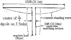
3.5Mhz. On this band each half of the “flat-top” plus about 17ft (5.18m) of each leg on the matching-section forms a fore-shortened or slightly folded up half-wave dipole. The remainder of the matching-section acts as an unwanted but unavoidable reactance between the electrical centre of the dipole and the feeder to the antenna tuner. The polar diagram is effectively that of a half-wave antenna. See figure 1.
7Mhz. The “flat-top” plus 16ft (4.87m) of the matching section now functions as a partially-folded-up “two half-wave in phase” antenna producing a polar diagram with a somewhat sharper lobe pattern than a half-wave dipole due to its colinear characteristics. Again, the matching to a 75 ohm twinlead or 50/80 ohm coaxial feeder at the base of the matching section is degraded somewhat by the unwanted reactance of the lower half of the matching section but, despite this, by using a suitable antenna tuner the system loads well and radiates very effectively on this band. See figure 2.
10Mhz. On this band the antenna functions as a two half-wave in-phase colinear array, producing a polar diagram virtually the same as on 7mhz. A reactive load is presented to the feeder at the base of the matching section but, as for 7mhz, the performance is very effective. See figure 3.
14Mhz. At this frequency the conditions are ideal. The “flat-top” forms a three-half-wave long centre-fed antenna which produces a multi-lobe polar diagram with most of its radiated energy in the vertical plane at an angle of about 14 degrees, which is very effective for dx working. Since the radiation resistance at the centre of a three-half-wave long-wire antenna supported at a height of half-wave above ground of average conductivity is about 90 ohm, and the 34ft (10.36m) matching section now functions as a 1:1 impedance transformer, a feeder of anything between 75 and 80 ohm characteristic impedance will “see” a non-reactive (ie resistive) load of about this value at the base of the matching section, so that the vswr on the feeder will be very nearly 1:1. Even the use of 50 ohm coaxial feeder will result in a vswr of only about 1.8:1. It is here assumed that 34ft (10.36m) is a reasonable average antenna height in amateur installations. See figure 4.
18Mhz. The antenna functions as two full-wave antennas fed in phase; combining the broadside gain of a two-element colinear array with somewhat lower zenith angle radiation than a half-wave dipole due to its long-wire characteristic. See figure 5
21Mhz. On this band the antenna works as a “long-wire” of five half-waves, producing a multilobe polar diagram with very effective low zenith angle radiation. Although a high resistive load is presented to the feeder at the base of the make-up section, the system loads very well when used in conjunction with a suitable antenna tuner and radiates very effectively for dx contacts. See figure 6.
24Mhz. The antenna again functions effectively as a five-half-wave “long-wire” but, because of the shift in the positions of the current anti-nodes on the flat-top and the matching section, as may be seen from figure 7, the matching or “make-up” section now presents a much lower resistive load condition to the feeder connected to its lower end than it does on 21mhz. Again, the polar diagram is multilobed with low zenith angle radiation.
28Mhz. On this band, the antenna functions as two “long-wire” antenna, each of three half-waves, fed in-phase. The polar diagram is similar to that of a three half-wave “long-wire” but with even more gain over a half-wave dipole due to the colinear effect obtained by feeding two three-half-wave antennas, in line and in close proximity, in-phase. See figure 8.
Construction
The Antenna
The dimensions of the antenna and its matching section are shown in Figure 9. The “flat-top” should, if possible, be horizontal and run in a straight line, and should be erected as high as possible above ground. In describing the theory of operation, it has been assumed that it is generally possible to erect the antenna at an average height of about 34ft (10.36m), which happens to be the optimum radiation efficiency on 1.8, 3.5 and 7mhz for any horizontal type antenna, in practice few amateurs can install masts of the optimum height of half a wavelength at 3.5 or 7mhz, and certainly not at 1.8mhz.
If, due to limited space available, or to the shape of the garden, it is not possible to accommodate the 102ft (31.1m) top in a straight line, up to about 10ft (3m) of the antenna wire at each end may be allowed to hang vertically or at some convenient angle, or be bent in a horizontal plane, with little practical effect upon performance. This is because, for any resonant dipole antenna, most of the effective radiation takes place from the centre two-thirds of its length where the current antinodes are situated. Near to each end of such an antenna, the amplitude of the current standing wave falls rapidly to zero at the outer extremities; consequently, the effective radiation from these parts of the antenna is minimal. The antenna may also be used in the form of an inverted-V. However, it should be borne in mind that, for such a configuration to radiate at maximum efficiency, the included angle at the apex of the V should not be less than about 120 degrees. The use of 14awg enameled copper wire is recommended for the flat-top or V, although thinner gauges such as 16 or even 18awg can be used.
The Matching Section
This should be, preferably, of open-wire feeder construction for minimum loss. Since this section always carries a standing-wave of current (and voltage) its actual impedance is unimportant. A typical, and very satisfactory, form of construction is shown in figure 10. The feeder spreaders may be made of any high-grade plastic strips or tubing; the clear plastic tubing sold for beer or wine siphoning is ideal.
If it is desired to use 300 ohm ribbon type feeder for this section, it is strongly recommended that the type with “windows” be used because of its much lower loss than that with solid insulation throughout its length, and its relative freedom from the “detuning” effect caused by rain or snow. If this type of feeder is used for the matching section, allowance must be made for its velocity factor (vf) in calculating the mechanical length required to resonate as a half-wave section electrically at 14.15mhz. Since the vf of standard 300 ohm ribbon feeder is .82, the mechanical length should be 28ft (8.5m). However, if 300 ohm ribbon with “windows” is used, its vf will be almost that of open-wire feeder, say .90, so its mechanical length should be 30.6ft (9.3m). This section should hang vertically from the centre of the antenna for at least 20ft (6.1m) or more if possible. It can then be bent and tied off to a suitable post with a length of nylon or terylene cord so as to be supported at above head-height to the point where, supported by a second post, its lower end is connected to the feeder.
The Feeder
The antenna can be fed by any convenient type of feeder provided always that a suitable type of antenna tuner is used. In the original article describing the G5RV antenna, published in the , then, RSGB bulletin November 1966, it was suggested that if coaxial cable feeder was used, a balun might be employed to provide the necessary unbalanced-to-balanced transformation at the base of the matching section. This was because the antenna and its matching section constitute a balanced system, whereas a coaxial cable is an unbalanced type of feeder. However, later experiments and a better understanding of the theory of operation of the balun indicated that such a device was unsuitable because of the highly reactive load it would “see” at the base of the matching or “make-up” section on most hf bands.
It is now known that if a balun is connected to a reactive load presenting a vswr of more than about 2:1, its internal losses increase, resulting in heating of the windings and saturation of its core (if used). In extreme cases, with relatively high power operation, the heat generated due to the power dissipated in the device can cause it to burn out. However, the main reason for not employing a balun in the case of the G5RV antenna is that, unlike un antenna tuner which employs a tuned circuit, the balun cannot compensate for the reactive load condition presented to it by the antenna on most of the hf bands, whereas a suitable type of antenna tuner can do this most effectively and efficiently.
Recent experiments by the author to determine the importance or otherwise of “unbalance” effects caused by the direct connection of a coaxial feeder to the base of the matching section had a rather surprising result. They proved that, in fact, the hf currents measured at the junction of the inner conductor or the coaxial cable with one side of the (balanced) matching section and at the junction of the outer coaxial conductor (the shield) with the other side of this section are virtually identical on all bands up to 28mhz, where a slight but inconsequential difference in these currents has been observed. There is, therefore, no need to provide an unbalanced-to-balanced device at this junction when using coaxial feeder.
However, the use of an unbalanced-to-unbalanced type of antenna tuner between the coaxial output of a modern transmitter (or transceiver) and the coaxial feeder is essential because of the reactive condition presented at the station end of this feeder which, on all but the 14mhz band, will have a fairly high to high vswr on it. This vswr, however, will result in insignificant losses on a good-quality coaxial feeder of reasonable length; say, up to about 70ft (21.3m). Because it will, inevitably, have standing waves on it, the actual characteristic impedance of the coaxial cable is unimportant, so that either 50 ohm or 80 ohm type can be used.
Another very convenient type of feeder that may be used is 75 ohm twinlead. However, because of the relatively high loss in this type of feeder at frequencies above about 7mhz, especially when it has a high vswr on it, it is recommended that not more than about 50 to 60ft (15.2 to 18.3m) of this type feeder be used between the base of the matching section and the antenna tuner. Unfortunately the 75 ohm twinlead in the UK is the receiver type; the much less lossy transmitter type is available in the USA. By far the most efficient feeder is the “open wire” type. A suitable length of such feeder can be constructed in exactly the same way as that described for the open-wire matching section. If this form of feeder is employed, almost any convenient length may be used from the centre of the antenna right to the antenna tuner (balanced) output terminals. In this case, of course, the matching section becomes an integral part of the feeder.
A particularly convenient length of open-wire feeder is 84ft (25.6m), because such a length permits parallel tuning of the antenna tuner circuit on all bands from 3.5 to 28mhz with conveniently located coil taps in the antenna tuner coils for each band, or, where the alternative form of antenna tuner employing a three-gang 500pf/section variable coupling capacitor is used the optimum loading condition can be achieved for each band. However, this is not a rigid feeder length requirement and almost any length that is mechanically convenient may be used. Since this type of feeder will always carry a standing wave, its characteristic impedance is unimportant, and sharp bends, if necessary, may be used without detriment to its efficiency. It is only when this type of feeder is correctly terminated by a resistive load equal to its characteristic impedance that such bends must be avoided.
Coaxial cable hf choke
Under certain conditions, either due to the inherent “unbalanced-to-balanced” effect caused by the direct connection of a coaxial feeder to the base of the (balanced) matching section, or to pick-up of energy radiated by the antenna, a current may flow on the outside of the coaxial outer conductor. This effect may be considerably reduced, or eliminated, by winding the coaxial cable feeder into a coil of 8 to 10 turns about 6in in diameter immediately below the point of connection of the coaxial cable to the base of the matching section. the turns may be taped together or secured by nylon cord.
It is important, of course, that the junction of the coaxial cable to the matching section be made thoroughly water-proof by any of the accepted methods; binding with several layers of plastic insulating tape or self-amalgamating tape and then applying two or three coats of polyurethane varnish, or totally enclosing the end of the coaxial cable and the connections to the base of the matching section in a sealant such as epoxy resin.
From RADIO COMMUNICATIONS, JULY 1984
The ‘Aerial’ Antenna Section
The balloon kite arrangement I use involves the Helikite Sky Hook or the Lightweight Helikite . The Sky Hook is larger than the ‘bird scaring’ range of lightweight Helikites, and will fly in wet weather. The two types of Helikite are highlighted.
Wind Max Altitude_Helium Capacity Lift No wind Lift in Wind Max
Vigilante Helikite 0.15 m3 0.03 Kg 0.15 Kg 25 mph 1,000 ft
Lightweight Helikite 0.15 m3 0.06 Kg 0.18 Kg 25 mph 1,300 ft
Skyhook Helikite 1.0 m3 0.4 Kg 1.5 Kg 28 mph 2,000 ft
Skyhook Helikite 1.3 m3 0.7 Kg 2.5 Kg 31 mph 2,500 ft
The Helikite Sky Hook will just about lift the quarter wave (40 metres) of number 14 flexiweave wire without wind, but any breeze at all takes it right up with the additional generated lift. The designed angle of flight of the Helikites is 45 degrees or a bit more, making it not quite a true vertical but certainly a lot more vertical than an inverted ‘L’.
To deploy the balloon/kite antenna, the 12 metre SCAM12 mast is nested at 2 metres, a 4 metre fibreglass stub is inserted into the top at the 40mm spigot. A 150 kg. breaking strain fishing swivel is attached to the top of the stub to keep twisting to a minimum. All attachments are made with 200 kg. breaking strain Kevlar line. On each side of the swivel is about 10 cm. of Kevlar line. The antenna wire to the Sky Hook is run from a small porcelain insulator at the swivel to the Helikite, with the last two metres being Kevlar attached to a small high strength porcelain insulator. Another swivel at the Helikite attachment point takes care of the last of the twisting. The final bit of additional Kevlar keeps any arc away from the attachment point and saves chasing the Helikite across the country as it flies to 1 to 2 thousand feet and drifts rapidly away. (My insurance has paid for two escapees that took off)
The Sky Hook is then released, the 40 metres of flexiweave antenna wire played out, and then the pump up mast is put into the full up position, SLOWLY, to avoid strain on the kite antenna wire. The soil of MY QTH (have a look at this link) is very sandy, but I am not far from the North Sea. The antennas for Top Band work well. Here is a plot of the Helikite antenna, shown with a ground loss of about 10 ohms which is a bit high. I have about 60 radials from 45 to 120 feet in length. I think this plot is conservative.
First, Balloons – How Big?????
Now we come to the part about launching a balloon supported tall vertical or protracted inverted L. First of all, you should be concerned about potential shock hazards and high noise levels resulting from wind-induced static. The solution at low power levels is to use a bleeding resistor (or inductor) to the antenna’s ground, high enough wattage )non-inductive) to discharge the static build up at an adequate rate while preserving the electrical characteristics of the antenna. (r > 100,000 ohms, an inductor value depends on frequency). Another way is to do it by making a spark gap. Use a very large gauge of copper wire, say #8. Solder the wire to your ground connection, and to the antenna wire, then with a fine saw, cut the wire, leaving just enough ‘spark gap’ to discharge the static build up, but not close enough to arc under transmit.
Unless you exceed a quarter wave by a significant amount on Top Band, static discharge is not a real problem. A half wave can begin to be a real problem. I have only tried an antenna higher than 60 metres once and there was a significant amount of ‘jolt’ when I touched the antenna feed point before attaching the antenna to the ATU. I normally use an SGC 230 auto tuner which also gives me 80 metres if I go ‘VHF’. Sometimes an ‘L’ network is used for high impedances encountered at 3/8 wave.
Back to the physics lesson, what about the physical (structural) ‘reality’ and security of such a setup. First, there are a few physical laws that control the balloon’s behaviour and here is the lesson.
Sizing for still-air conditions
Material specification. (also good for a small to medium kite)
Thin copper wire: AWG 28 : 2081f/lb (.0005 lb/f); 65.31ohm/1000′ (source ARRL Handbook.)
Support line: 40 pound test BRAIDED NOT MONOFILAMENT at .0001 lb/f (conservative estimate).
I use the wire and the line taped about every three feet. I leave about three feet of antenna wire dangling at the top to keep high voltage away from the support line. I learned this the hard way after bursting two balloons at key down (400 watts) and losing a balloon when the support line burned through. For higher power, larger wire is used, again, the source of the weight of the wire is the ARRL Handbook.
Balloons and Physics
As per Archimedes’s principle, the upward force developed by a balloon is related to the weight of the air displaced by the balloon volume.
Actually the balloon should be sized to carry this net buoyancy (.8045lb) + the weight of the helium (s.g. = .1308 that of air) it carries + the weight of the balloon envelope.
For example, at 500′ ASL you want to launch a 200′ high (= 700′ ASL) balloon able to procure sufficient lift for a .8045 lb antenna and line payload.
Lets suppose that a 40 inch (3.33′ ) diameter of .5 lb envelope weights is available.
By the way, I use Kent Balloons here in the UK for my balloons, but any large commercial balloon supplier will have them. Helium can be obtained from any commercial supplier of industrial gases, here I use BOC, which is listed in the Yellow Pages under industrial gases.
THE CALCULATIONS
Density of air at 500′ ASL = .0754 lb/pi3, at 700 ASL = .0750 lb/pi3
Volume = .5236 x d3 = 19.39 pi3
At 700′ ASL ; Weight of air = 19.39 x .0750 = 1.454 lb
At 500′ ASL ; Weight of helium = 19.39 x .0754 x .1308 = .191 lb
Net buoyancy at 700′ ASL = 1.454 – .191 – .4 = .863 lb
In this case, two of these balloons would be ok for the proposed setup. One at the top of the support line, the other about ten feet down to dampen the sway of the antenna in the wind.
Effects of the wind
In fluid mechanics textbooks, you can find formulas to determine the drag force applied by moving air upon a stationary spherical object. (the balloons)
Fd = Cd p V2 A / 2
Fd : drag force ( lb ) Cd : drag coefficient (no dimension)
V2 : Velocity of the wind squared ( f2/sec2 )
A : Center area of the sphere ( f2 )
Cd = .4 for Re ( Reynold number) < 350,000 Cd = .2 for Re > 350,000
Re = D V / u
D diameter of the sphere (feet)
V Speed of the wind (feet/sec)
u (nu) Kinematic viscosity of air = ~.00016 (f2/sec)
Below is a table that shows the evolution of horizontal pressure (in pounds) induced by various wind velocities (mph) on various balloon diameters (feet)
Horizontal wind-induced pressures on a spherical balloon: Fd (pounds)
V (mph) 3′ 3.33′ 4′ 5′ 6′ Diam
10 .71 .88 .66 1.02 1.5
15 .83 1.03 1.5 10.7 15.4
20 1.5 1.83 2.63 4.1 5.9
30 3.33 4.1 5.9 9.2 13.3
40 5.9 7.3 10.5 16.5 23.7
Here, I will limit the analysis to a worst case scenario, where I will use only common sense to evaluate resulting strain on the antenna support wire. I did that to the table above to generate the table below. Let’s keep in mind these values are somewhat on the safe side. Also, keep in mind that the balloon lifted antenna will have gone almost horizontal by the time the wind speed hits about 15 mph. This is a safety exercise after all.
Estimated side wind-induced strain on the antenna wire (pounds)
V (mph) 3′ 3.33′ 4′ 5′ 6′ Diam
10 3.9 4.1 3.1 4.7 6.9 Safe
zone
15 3.9 4.8 7.0 10.7 15.4
20 7.0 8.5 12.2 19.0 27.4
30 15.4 19.0 27.4 42.7 61.8 Risk
zone
40 27.4 33.9 48.8 76.7 110.
One last table-the physical properties of air
Altitude (ASL) Air pressure Air density Air viscosity
feet lb/f2 lb/f3 f2/sec
0 2116.2 .0765 .000156
1000 2040.9 .0743 .000162
2000 1967.7 .0720 .000164
Practical Considerations
The balloon envelope material quality is also something you should consider before attempting any lift off. If not, you may experience a short lived project. We’ve all air blown party rubber balloons to their max, just to realize that the next day they had shrunk to half their size. The reason being that, due to pressure differential between inside and outside of the stretched envelope, air will just sift through it. Rubber is an elastomeric material built around long organic molecular chain attached one to the other through ramifications (something like a tree), and there are ‘holes’ between these chain elements. Air made up of molecular oxygen, nitrogen, and carbon dioxide eventually finds its way through. So if molecular elements like O2 and N2, that are many times the size of atomic helium (He) can do that, you can imagine how helium would act considering the wide open barn doors these ‘holes’ are, relative to its size.
I don’t think a normal small ‘party’ balloon would be able to retain its full size for more than a couple of hours. So not any off the shelf stock will suffice. That is why I use Mylar balloons instead of large rubber party balloons to support my antennas on calm-ish nights. Sometimes I will use weather balloons that have enough helium to stay up even if a significant quantity gets out.
I have used 8 foot weather balloons, five foot rubber balloons, and Mylar balloons. The Mylar balloon is similar to the Helikite’s and the Mylar envelope will stay inflated for days, whereas the rubber balloons are good for only about eight hours. The weather balloons stay up all night, but really lose size after about five hours. The five footers stay up about ten hours, but they are getting pretty sagged by then.
Now…A word about safety
The DO NOT List
Do not fly your kite or balloon near power lines of any description. If the flying line becomes wet it will become a conductor of electricity with lethal consequences. A highly conductive aerial wire will only add to the considerable danger. Also, remember if the kite or balloon breaks its tether, the dragging wire can cause havoc with power lines some distance away.
Do not fly your kite or balloon if there is the possibility of thunder or lightning. You don’t want to become a lightning conductor. Benjamin Franklin was stupid enough for us back in 1752.
Read the above again!!!!
Do not fly your kite or balloon if high winds are forecast. (Check the hour by hour forecast for your area at The Weather Channel.) You can put in your post code, zip code, or city and this site will give you a good indication if it is go or no go as you can see wind speed and direction forecasts hour by hour. Sometimes the winds will drop overnight so that is why I will use a balloon antenna lifter of some sort then. A dead calm will bring down the kite. In the dark, that is a pain!
Do not fly your kite or balloon near a road, car park, railway line or where there are any moving vehicles.
Do not fly your kite or balloon near farm animals, bird or animal sanctuary. You could frighten or alarm them.
Do not fly your kite or balloon within 5 kilometres or 3 miles of an airfield but check the local regulations in your country.
Do not fly your kite or balloon higher than the legal limit in your country unless you have obtained permission from your local or national Air Regulation Authority. 60 metres is internationally recognised as the limit of vertical height above terrain.
Do not fly your kite or balloon near trees or buildings or your kite may become entangled. There is always air turbulence near them so they are best avoided.
The DO List
ALWAYS use a line in conjunction with the kite or balloon antenna element, NEVER just the antenna wire.
ALWAYS wear gloves to protect your hands. I use leather gardening gloves to prevent painful burns.
ALWAYS ensure that you or your clothing are not tangled together with the flying line or the antenna wire.
ALWAYS seek permission of the landowner before flying, unless it is your property, then just soft soap the neighbours when your kites lands on their roof.
ALWAYS check the wind speed before flying, the higher the wind the more difficult the kite or balloon is to recover.
ALWAYS fly the kite on line the strength of which is determined by its size. The correct line for most lifter kites or balloons is at least 160 pounds.
ALWAYS launch and retrieve the kite or balloon from your hand….never run with it as you could fall and be injured, and look a prat like Charlie Brown!
ALWAYS carry sunglasses (Polarised ones are best) to keep an eye on your line/antenna in the daylight. At night, a torch or flashlight is handy also.
ALWAYS wind the flying line in a figure of eight onto the winding handle, otherwise you may never get the line off again!
ALWAYS replace the flying line if it shows any sign of becoming frayed or damaged.
ALWAYS untie any knots on the line which are not there by your intention. Incorrectly tied knots seriously weaken the flying line.
ALWAYS check the security of knots before flying. I have lost good kites when a knot went, and it was 200 feet in the air.
ALWAYS avoid anyone touching the antenna when you are transmitting. Believe it or not, kids do like kites.
ALWAYS prevent anyone else from interfering with the kite or your equipment while you are operating.
Another few bits of information:
It is important to understand the forces which are involved with kites and balloons. The larger the kite or the balloon, the more it will lift but also the forces of nature acting on it will also be that much more difficult to contend with. A larger kite will fly in mild winds but it certainly will become tougher to handle in strong winds. Should you launch a large kite in reasonable wind and some time later the wind strength increases you could be in some difficulties whenever you attempt to recover it. During the initial learning stages, just be sensible about the wind conditions you are attempting to fly in. The optimum size for a kite is its ability to lift things for any given wind and to be controllable by the operator. It is quite easy to launch a kite into the air but it is another matter entirely when you want to recover it. That is why my kites have been made to reasonable dimensions. They have to have enough lift and be within the ability of a single person to safely fly it in the widest range of wind conditions.
TURBULENCE
Near trees and buildings there is always air turbulence where the wind is tunneled or down draughts could upset the flying of your kite. If you fly upwind of the obstructions the kite is liable to become entangled in branches or obstructions on buildings. The wind close to the ground is usually not as smooth and laminar as it is higher up. Once the kite is airborne you will notice that it becomes steadier with height. You will also find that the wind is generally stronger the higher up the kite is flown. This can be felt with the increased pull on the flying line. Another thing to watch out for is the turbulence created by hills, as this turbulence can extend to a considerable height.
THE FLYING LINE
The choice of flying line is important. Braided fishing line is best and the required strength is at least 160 pounds.. Do not be tempted into using cheap polypropylene line, it will not stand up to the abuse kite flying will give it. Go to your nearest fishing tackle shop and consult with the shopkeeper. Use only the best available. 130 pounds will do, but it also reduces the safety margin.
Author Unknown
Back to top^
Coax balun on PVC form
My experience is that PVC works fine as a form for high Q RF coils. I’ve measured Qs of up to 450 on loading coils wound on PVC pipe. I’ve appended a paper I wrote on measurements of coaxial baluns wound on PVC forms.
Having access to a Hewlett-Packard 4193A vector impedance meter at work, I have made measurements on a number of baluns, coaxial and otherwise. For my beams I was particularly interested how many turns and on what diameter are optimum for air core coaxial baluns, and what the effect of bunching the turns was (formless). Using the remote programming capability of the HP4193A along with an instrument controller, I measured the magnitude and phase of each balun’s winding impedance at 1 MHz intervals from 1 to 35 MHz. For comparison, I also made measurements on a commercial balun which consists of a number of ferrite beads slipped over a short length of coax. I’ve appended some of these measurements so you can draw your own conclusions.
PVC pipe was used for coil forms. The 4-1/4 inch diameter baluns were wound on thin-walled PVC labeled “4 inch sewer pipe”. This material makes an excellent balun form. It’s very light weight and easy to work with, and I obtained a 10 foot length at the local Home Depot for about 3 dollars. The 6-5/8 inch diameter forms are 6 inch schedule 40 PVC pipe which is much thicker, heavier, and more expensive.
Each test choke was close-wound on a form as a single-layer solenoid using RG-213 and taped to hold the turns in place. The lengths of cable were cut so there was about 2 inches excess at each end. This allowed just enough wire at the ends for connections to the HP4193A’s probe tip. After data was collected for each single-layer configuration, the PVC form was removed, the turns were bunched together and taped formless, and another set of measurements was taken. I have only included the “bunched” measurements in the table for one of the baluns, but the trend was the same in each case. When compared to the single-layer version of the same diameter and number of turns, the bunched baluns show a large downward shift in parallel self-resonance frequency and poor choking reactance at the higher frequencies.
Interpreting the Measurements
All the baluns start out looking inductive at low frequencies, as indicated by the positive phase angles. As the frequency is increased, a point is reached where the capacitance between the windings forms a parallel resonance with the coil’s inductance. Above this frequency, the winding reactance is reduced by this capacitance. The inter winding capacitance increases with the number of turns and the diameter of the turns, so “more is not always better”.
The effects of a large increase in inter winding capacitance is evident in the measurements on the balun with the bunched turns. This is probably a result of the first and last turns of the coil being much closer together than the single-layer coil. An important requirement of these baluns is that the magnitude of the winding reactance be much greater than the load impedance. In the case of a 50 ohm balanced antenna, the balun’s winding impedance is effectively shunted across one half the 50 ohm load impedance, or 25 ohms. A reasonable criteria for the balun’s winding impedance for negligible common mode current in the shield is that it be at least 20 times this, or 500 ohms. The measurements show, for example, that 6 turns 4-1/4 inches in diameter meet this criteria from 14 to 35 MHz.
The measurement data also reveals the power loss these baluns will exhibit. Each of the measurement points can be transformed from the polar format of the table to a parallel equivalent real and reactive shunt impedance. The power dissipated in the balun is then the square of the voltage across it divided by the real parallel equivalent shunt impedance. While this calculation can be made for each measurement point, an approximate number can be taken directly from the tables at the parallel resonance points. At 0 degrees phase angle the magnitude numbers are pure resistive. I didn’t record the exact resonance points, but it can be seen from the tables that the four single-layer baluns are all above 15K ohms, while the ferrite bead balun read about 1.4K. These baluns see half the load voltage, so at 1500 watts to a 50 ohm load, the power dissipated in the coaxial baluns will be less than 1.3 watts, and the ferrite bead balun will dissipate about 13.4 watts (neglecting possible core saturation and other non-linear effects). These losses are certainly negligible. At 200 ohms load impedance, the losses are under 5 watts for the coaxial baluns and 53.6 watts for the ferrite beads.
Conclusions
– A 1:1 coaxial balun with excellent choking reactance for 10 through 20 meters can be made by winding 6 turns of RG-213 on inexpensive 4 inch PVC sewer pipe.
– For 40 or 30 meters, use 12 turns of RG-213 on 4 inch PVC sewer pipe.
– Don’t bunch the turns together. Wind them as a single layer on a form. Bunching the turns kills the choking effect at higher frequencies.
– Don’t use too many turns. For example, the HyGain manuals for my 10 and 15 meter yagis both recommend 12 turns 6 inches in diameter. At the very least this is about 3 times as much coax as is needed, and these dimensions actually give less than the desired choking impedance on 10 and 15 meters.
Measurements
————
Magnitude in ohms, phase angle in degrees, as a function of frequency in Hz, for various baluns.
6 Turns 12 Turns 4 Turns 8 Turns 8 Turns Ferrite
4-1/4 in 4-1/4 in 6-5/8 in 6-5/8 in 6-5/8 in beads
sngl layer sngl layer sngl layer sngl layer bunched (Aztec)
———- ———- ———- ———- ———- ———-
Frequency Mag Phase Mag Phase Mag Phase Mag Phase Mag Phase Mag Phase
1.00E+06 26 88.1 65 89.2 26 88.3 74 89.2 94 89.3 416 78.1
2.00E+06 51 88.7 131 89.3 52 88.8 150 89.3 202 89.2 795 56.1
3.00E+06 77 88.9 200 89.4 79 89.1 232 89.3 355 88.9 1046 39.8
4.00E+06 103 89.1 273 89.5 106 89.3 324 89.4 620 88.3 1217 26.6
5.00E+06 131 89.1 356 89.4 136 89.2 436 89.3 1300 86.2 1334 14.7
6.00E+06 160 89.3 451 89.5 167 89.3 576 89.1 8530 59.9 1387 3.6
7.00E+06 190 89.4 561 89.5 201 89.4 759 89.1 2120 -81.9 1404 -5.9
8.00E+06 222 89.4 696 89.6 239 89.4 1033 88.8 1019 -85.7 1369 -15.4
9.00E+06 258 89.4 869 89.5 283 89.4 1514 87.3 681 -86.5 1295 -23.7
1.00E+07 298 89.3 1103 89.3 333 89.2 2300 83.1 518 -86.9 1210 -29.8
1.10E+07 340 89.3 1440 89.1 393 89.2 4700 73.1 418 -87.1 1123 -35.2
1.20E+07 390 89.3 1983 88.7 467 88.9 15840 -5.2 350 -87.2 1043 -39.9
1.30E+07 447 89.2 3010 87.7 556 88.3 4470 -62.6 300 -86.9 954 -42.7
1.40E+07 514 89.3 5850 85.6 675 88.3 2830 -71.6 262 -86.9 901 -45.2
1.50E+07 594 88.9 42000 44.0 834 87.5 1910 -79.9 231 -87.0 847 -48.1
1.60E+07 694 88.8 7210 -81.5 1098 86.9 1375 -84.1 203 -87.2 778 -51.8
1.70E+07 830 88.1 3250 -82.0 1651 81.8 991 -82.4 180 -86.9 684 -54.4
1.80E+07 955 86.0 2720 -76.1 1796 70.3 986 -67.2 164 -84.9 623 -45.9
1.90E+07 1203 85.4 1860 -80.1 3260 44.6 742 -71.0 145 -85.1 568 -51.2
2.00E+07 1419 85.2 1738 -83.8 3710 59.0 1123 -67.7 138 -84.5 654 -34.0
2.10E+07 1955 85.7 1368 -87.2 12940 -31.3 859 -84.3 122 -86.1 696 -49.9
2.20E+07 3010 83.9 1133 -87.8 3620 -77.5 708 -86.1 107 -85.9 631 -54.8
2.30E+07 6380 76.8 955 -88.0 2050 -83.0 613 -86.9 94 -85.5 584 -57.4
2.40E+07 15980 -29.6 807 -86.3 1440 -84.6 535 -86.3 82 -85.0 536 -58.8
2.50E+07 5230 -56.7 754 -82.2 1099 -84.1 466 -84.1 70 -84.3 485 -59.2
2.60E+07 3210 -78.9 682 -86.4 967 -83.4 467 -81.6 60 -82.7 481 -56.2
2.70E+07 2000 -84.4 578 -87.3 809 -86.5 419 -85.5 49 -81.7 463 -60.5
2.80E+07 1426 -85.6 483 -86.5 685 -87.1 364 -86.2 38 -79.6 425 -62.5
2.90E+07 1074 -85.1 383 -84.1 590 -87.3 308 -85.6 28 -75.2 387 -63.8
3.00E+07 840 -83.2 287 -75.0 508 -87.0 244 -82.1 18 -66.3 346 -64.4
3.10E+07 661 -81.7 188 -52.3 442 -85.7 174 -69.9 9 -34.3 305 -64.3
3.20E+07 484 -78.2 258 20.4 385 -83.6 155 -18.0 11 37.2 263 -63.2
3.30E+07 335 -41.4 1162 -13.5 326 -78.2 569 -0.3 21 63.6 212 -58.0
3.40E+07 607 -32.2 839 -45.9 316 -63.4 716 -57.6 32 71.4 183 -40.5
3.50E+07 705 -58.2 564 -56.3 379 -69.5 513 -72.5 46 76.0 235 -29.6
Ed Gilbert, WA2SRQ
Where Do I Go from Here?
Some thoughts on your first antenna for HF
By Bob Raynor, N4JTE
Okay so you got your ticket and passed the exam as your entry into the world of amateur radio, soooooo are you bored yet? Hope not, because we are finally seeing some sunspots which allow your new voice privileges to be explored on 10 meters as opposed to the two meter stuff that might not be quite what you were hoping for. BUT if you have ventured into the next step and got your General ticket, I would like to give you a basic guideline on your HF antenna possibilities and perhaps answer a few questions along the way.
Your expectations:
I have been doing the ham thing for a lot of years and my addiction to the hobby may not become the same for you, but I think it’s safe to say we all want to be heard well enough to have a qso or at least get a fake 5-9 from a DX contester after yelling back at them in a relatively short time. That said, once on the air for awhile you will make friends and even be able to recognize their voices before hearing their callsigns! This is what keeps old farts like me and others coming back to radio at ridiculous hours, like saying hello to my friend in England G0EVY at 1am or checking in with the HHH net at 4am local to say hello to friends inAustralia andNew Zealand. The excitement of being able to this with some homebrew wire in the trees NEVER gets boring!
It has gotten to the point where I don’t even have to explain these bizarre hours to my xyl, got her trained, so to speak, as long as the garbage is taken out, mortgage paid, the wood chopped for the fireplace and the driveway shoveled so she can get to work; while I put up a wire beam for 80 meters halfway into my neighbors yard, all is fine in my ham world. Yeah right!
Anyway, point of this short article is to try to focus our newly licensed Ham brethren and give you folks some tried and true antenna advice before you get sucked into buying a commercial antenna you can build yourself or more importantly avoid wasting hours and money on some magic internet antenna.
Timing is Everything:
As a newly licensed ham, you have joined us after a pretty long dry spell, propagation wise. Band conditions on the upper bands like 10, 15 and 20 meters are showing some incredible signs of life. What this means is you don’t need a $5000 tower and beam to speak to another ham half way around the world, propagation will do most of the work with the antennas I am going to describe and these conditions should last a few years, and this stuff will cost you less than you might spend for a month of internet service!
What’s your Preference?
So many frequencies and only so much time to play on the radio! Good time to make some choices, are you ultimately trying to see how far away you can be heard, or maybe you’ve got another new ham friend some miles away you want to keep in touch with? Or even maybe you are more technically inclined and want to explore antenna building or perhaps contesting? Time for you to focus a little bit, after a little while on SSB you’ll find a niche of interest, BUT; your antenna is your key element to getting it done. A $2000 radio will become an expensive doorstop without studying, reading and building the best antenna you can fit in your backyard.
My first choice in antennas has always been some configuration made from wire and usually for two bands, 40 meters and 80 meters, my reason being that a monoband antenna is easier to build and easier to match efficiently to your radio, I have designed/ reviewed various multi-band wires, see “ribbon” and “G5RV” in old eham articles under my call, but the need for a multiband antenna is probably a good thing for a new ham to explore so I will present a few. BUT; you new generals will have to take the time to research the actual dimensions and construction, this isn’t a “ how to article,” what I do want to present is what actually works and will give the most bang for the buck and get you reading some antenna theory books as opposed to advertisements. Google is our friend if you need more info on the following antennas or email me at my QRZ page.
Gonna give my choices as based on best to last preference for starter efficient antennas from my own personal experience at my location, your mileage may vary.
Multiband Homebrew Wire antennas:
CENTER FED DOUBLET
1: Put up the longest, highest, flattest center fed wire you can fit in your yard, nothing wrong with the ends hanging down near non conductive end supports to add additional length. This antenna needs to be fed with open feed ladderline and will require a tuner to match efficiently to your 50 ohm radio. If you can get at least 75% of the length of your lowest band wavelength up in the air, this antenna will make your day on a lot of frequencies. My first choice for a new ham who wants to explore a bunch of bands.
FAN DIPOLE
For shape reference only!
This kind of antenna allows the use of direct match to 50 ohm coax and should not need a tuner and will allow operation on mutibands with a little sweat equity on the construction side. Like I said in preamble, read up on this one, might fit your yard and your radio needs.
Not going to spend much more time on multi band antennas because once you have narrowed your focus as a newer ham you’re going to want to be louder than the guys using them, so next, a little time will be devoted to how to double your power out and increase that skip distance thing you memorized on your test!
Oh yeah; I GUARANTEE that either of the above antennas will work as well as or better than anything sold commercially for 10 times the price!
AND; I am aware it is a short list, counting on my antenna gurus reading this to jump in and expand!
But before someone else points out the obvious , let it be known that almost any piece of wire will get you on the air and be heard somewhere, but with a little homework you will enjoy designing something to fit in your backyard that will expand your horizons. During WW2 a little toy called a Slinky, yeah that thing, was used to successfully communicate on the battlefield! And hula hoops became super magnetic loops able to work the world at will, just kidding about that one.
SO YOU WANT TO BE LOUD WAY OUT THERE?
Well that’s going to take a little work if you are willing to play with some wire.
On the upper bands pretty much everyone has a commercial, expensive beam on some sort, on a tower, not to worry, the same can be done at nominal cost with wire. On 40 and below a wire gain antenna is the way to go and not hard to do. And once you get a little more into phased reversible wire arrays you will be truly competitive with most of the tower/ commercial store bought beam guys on ANY band.
1: YE GOOD OLD DIPOLE!
The most efficient, easy to build mono band antenna out there. Unless you are getting creamed in some contest with the big guns firing up their $20,000 stations, you will be heard, HOW?; because by hook or crook you figured out a way to get that sucker up in the air at around ½ WL on the band of your choice! If DX is your new found interest then broadside it to the NE/SW
If tight for room or lack of supports an inverted vee up as high as possible will give good results also.
Build your own and you will be amazed on any band with a dipole, especially with the emerging sunspots. The secret to DX is the lowering of your take off angle into the ionosphere and getting that first skip into the, direction/ area you’re chasing, a good high dipole can do it, other designs do it better however.
2: WIRE GAIN ANTENNAS:
It is beyond the scope of this article to explain the intricacies of multi element beam antennas like the one way up there on your neighbor’s tower.
Wire beams are relatively simple to build and extremely cheap! Commercial aluminum beams for any band are based on the property of the dipole.
By adding some correct length and spaced wires in front of, or behind, or both, of a dipole you have now focused the antenna in a narrower direction, another way to define gain.
Think of a flashlight as opposed to a candle and you will get the jist of focused energy in a specific direction.
Simple Two Element Wire Beam:
For shape reference only.
The addition of one wire 5% longer behind a dipole in the same plain will give you 3dbd of gain, in other words double your ERP; effective radiated power.
So that new 400 watt amp you saved up for will now have 800 watts going into the ionosphere. Oh yeah the extra power out works on receive also, adding an additional S unit and better signal to noise ratio for your hearing pleasure! You are focusing your transmitted signal in a smaller slice of the compass, helping diminish annoying signals off the side and the back.
This concept is applicable for every band from 2 meters to 160 meters; the spacing and between the two elements is subject to many variables and worth studying as is the possible shapes, quads, yagi, quagi etc.
The usual spacing between the wires for most gain is around .15WL.
If you have successfully built a dipole and remember the formula of 468/freq to achieve your ½ wl wire you are well on your way to using a little high school algebra to build your first beam antenna.
This process of free gain will open up an incredible arena of potential projects that will only be limited by your imagination and your commitment to studying the immutable laws of physics often contrary to a good portion of the advertisements we are all bombarded with everywhere.
Another worthy wire design is called a MOXON antenna with folded in elements that will fit where some wire beams will not. The moxon is a fun antenna and worth some serious study if you are plagued by loud stations behind you as it has very good front to back, meaning you will have an easier time hearing the station you are looking at.
Single Wire Gain Antennas:
About the only true single wire antenna that has 3db gain over a dipole is an EDZ, extended double zepp. These can be really long but if you have the room and tall enough supports this antenna will give you the same gain as a two element beam in two opposite directions. Mine has been up for years and has proven itself as the best narrow beam width single wire I have tried. Collinear antennas are a little shorter but have less gain so I stick with the EDZ.
Point being, as a new amateur either one might fit your needs so it’s worth the homework.
Getting Up In The Air:
The higher the band the smaller the antenna, nice little piece of physical law. Consider a 2 meter or a 10 meter wire beam built on the principals described above. Small enough to build and hang from any available tree and leave a string hanging from one corner to change directions, remember you built a directional beam, primitive maybe but mucho times better than the stub on your 2 meter hand held.
NO TREES ? Try something like below:
 For an inverted vee or center of a dipole an easy to get 40 ft in the air pole for $50 is pictured. I use these things all the time in beam and vertical experiments They are 25ft extended and attached to a 2×4 and then to post holed 4×4, no concrete or help needed to install alone. Check fiberglass flag poles or Spider poles.
SUMMARY:
I suggest the best thing for a newly licensed ham to do is to get on the air and start chatting with people. You can ask them what antenna they are using and make your own deductions. Join a WAS net, like CCN or OMISS and see what you like or dislike about your present antenna. Determine if you have a favorite band that fits your interest and maybe upgrade to a mono band wire beam.
This article is a very cursory look at starter antennas and methods that will work great without killing your checkbook. Once you start down the road of designing and building your own antennas you will be addicted to this very important facet of our hobby and who knows, maybe you will writing a better article in the near future!
Tnx for reading,
N4JTE
NVIS Tests of Three 40-Meter Antennas by Bill Savage, K3AN
The July, 2000 issue of QST Magazine contained an article by N6BT titled “Everything Works.” The author laid out his ideas on the relative performance and enjoyment factor of different antennas, from a light bulb on a 4-foot post to stacked Yagis on a tall tower. He related his own experience as a newby ham, thinking his first antenna was pretty good until he put up his second one, and so on. He also described his light bulb antenna, mounted on the wooden post, with a ferrite bead choke balun to minimize feedline radiation. With that light bulb and a 100-Watt transceiver he actually completed contacts to every continent on 10 Meters. “Everything Works” indeed!
I’ve had some epiphanies of my own concerning antennas. I still remember getting active once again in early 1980’s, with a used Knight R-100 receiver and T-150 transmitter. Upon bringing them home I was so anxious to test them that I stapled 33 feet of wire to the basement ceiling joists and ran a ground to the nearby copper water service entrance pipe. With the T-150’s pi-network I was able to load that wire and actually made contacts on 40-Meter CW (at night) as far as 500 miles away, much farther than expected. The antenna was near an outside wall, but it was no more than four feet above the surface of the ground outside.
Another epiphany occurred when I found out how poorly a 130-foot inverted L performs on 17-10 Meters compared to a smaller and slightly lower delta loop antenna. If I had never put up the delta loop I would have remained fat, dumb and happy with the L, which I had originally decided to use since it’s one of L. B. Cebik’s, W4RNL (SK) “five favorite backyard wire antennas.”
In some recent conversations and emails with local hams, I became interested in antennas for NVIS communications. Searching the web got me to some sites that attribute almost magical properties to very low antennas for short-range communication. Does a really low dipole outperform a higher antenna? There was only one way to find out. I borrowed some items to construct one new dipole, and pressed our Field Day 40-Meter dipole into service as well, so with my Daiwa 4-position coax switch I could quickly switch between them as well as my existing Inverted L. I present the three candidates below.
The Inverted L is a 130-foot insulated 18-gauge “stealth” wire running vertically up from near ground level about 60 feet into the top of a tall oak tree, and from there horizontally over to another tall tree. It is tuned at the base with an SGC-230 remote autotuner, with a ferrite choke balun on the feedline and the DC wires. There are seven insulated radials ranging in length from 25 to 50 feet, “buried” under a few inches of mulch (no grass on my heavily wooded lot). The total length of coax back to the coax switch is 62 feet. With the tuner, this antenna works on all bands 160-10 Meters. The SWR is 1.6:1 or less throughout the 40-Meter band, again thanks to the remote autotuner.
The traditional dipole is 66 feet of 14 gauge bare copper, stranded antenna wire, supported at the center by a tall pine tree. The feed point is 30 feet off the ground. The wires slope slightly downward a foot or so, toward support trees beyond either end. There’s a ferrite choke balun at the feed point. The total length of coax back to the coax switch is 94 feet. The SWR measures 1.3:1 at the bottom of the band, is 1.2:1 at 7.05 and 7.1 MHz, and rises to 1.8:1 at the top of the band.
The NVIS dipole is about 65 feet of insulated 16-gauge wire (one conductor of a zip cord pair) supported at the center and beyond each end by tree trunks, seven feet off the ground. This antenna also has a ferrite choke balun at the feed point. In accordance with the article that described this antenna, I placed three 70-foot runs of insulated 16-gauge wire on the ground in parallel with the antenna wires. One of the three wires is directly under the antenna and the others are eight feet either side of the first one. The total length of coax back to the coax switch is 113 feet. The SWR on this antenna was remarkably low, measuring 1.3:1 at the bottom of the band, 1:1 at 7.05 and 7.1 MHz, and rising to 2.4:1 at the top of the band. To be honest, I was both surprised and puzzled by the low SWR at resonance, but that’s what it was.
All coax is RG-8X. SWR measurements were made at the shack end of the cables. Even a hundred feet of RG-8X doesn’t have very much loss at 7 MHz so I wouldn’t expect the SWR measurements to be very different at the feedpoints. Only the coax run to the Inverted L is weathered (almost seven years now). The coax to the two dipoles has only been outside for a couple of Field Days. Over the course of several days I made 35 measurements of received signal strengths on stations ranging from 55 miles to as far away as 650 miles. I also contacted 14 of those 35 stations and asked them for reports from my end. In all cases the three antennas were identified to them as A, B and C, to try to prevent “confirmation bias” (Google it) from influencing the results.
Typical daytime 40-Meter QSB, while not as great as the fading on nighttime DX paths, still offers a challenge to making accurate comparison readings. Once I saw that the dipole at 30 feet was providing the strongest signals, I put its coax in the middle of three positions on the antenna switch. Then I would switch back and forth repeatedly between the two dipoles until I saw a pattern. This process was repeated between the dipole at 30 feet and the L. I used stations checking into South CARS for some of the measurements, and in some cases they transmitted for too short a time for me to accurately read the three antennas. Those stations were discarded from the results. By the way, I found that watching the bargraph S meter display on my Icom Pro 3 was a lot easier than watching the twitching D’Arsonval panel meter. Also, the Daiwa coax switch survived the several hundred switch position changes just fine.
So How’d They Do?
The dipole at 30 feet, which I will hereafter call the reference dipole, was the clear winner. Only three of the 35 stations had signal strengths on the L that were the same as on the reference dipole. The other 32 were less. None of the 35 received signals on the low dipole matched the signal strengths on the reference dipole. Also, all 14 respondents said the reference provided the strongest signal. Between the low dipole and the Inverted L, the received signal on the L was stronger 15 times, the two were equal 10 times, and the low dipole was stronger 10 times. Statistically that has to be considered a draw.
Compared to the reference dipole, the low dipole was always one to three S-units lower. The Inverted L was in that same range of one to three S-units most of the time, but there were three signals that were equal to the reference dipole and three signals that were four S-units down. The low dipole was as much as three S-units better than the L on the close-in stations (under 120 miles), but still not as good as the reference dipole. I have to conclude that, although it doesn’t put out the strongest signal, the low dipole works remarkably well for NVIS communication.
One of my pet peeves is seeing a review of a new antenna that uses mostly superlatives to describe it. OK, but what did you compare it to? A dipole at 30 feet? A triband yagi at the same height as your new Whiz-Bang Mark VI? You compared it to nothing else? Then how do you know it’s really performing well? After all, a light bulb was once used to complete the WAC award on 10 Meters. Yet no one would claim that’s a great antenna.
Oh, you used to have a different antenna and the new one seems to work better? Were the SFI and the A and K indices the same when the old antenna was up? How about time of day, and QRN and QSB conditions? My point is that unless you can instantly switch back and forth between the antennas being compared, your results should be taken with a big grain of salt. You also need to run a lot of tests, and record the results of each.
Lacking this capability, trying to work through a DX pileup is a pretty good way to determine how well your one-and-only antenna performs. Can you usually or often crack the pileups with just a few calls, or do you always have to wait in line, calling repeatedly and maybe never getting through?
You’re not a DXer? You can run the same test with any of the special event stations that pop up on the bands nearly every weekend. The recent Original 13 Colonies stations attracted some moderate pileups. How long did it take you to get through? Also, these stations usually give honest signal reports; not everyone is “five-nine.” How did your report compare to other reports the station gave out? Listen for a while and write them down.
But like me with my Inverted L, you still don’t know if something else would work better without putting up a second, different antenna, and testing the two. As the QST article says, “Everything Works,” even a dipole seven feet off the ground. It can be a lot of fun, as well as quite educational, to determine for yourself what works better.
K3AN
Spiderbeam in Germany make a series of the unique antennas.
Go to this link Spiderbeam Antennas and have a look at how they are made. Spiderbeams do have some unique features and perform extremely well.
73, Lee ZL2AL
Build a 2M yagi antenna from recycled materials. It is not difficult and you can save the environment. Go to this link Recycled TV Antenna
73, Lee ZL2AL
How a 1:4 Guanella-Balun (Current-Balun) Operates – ByJerry Sodus, KM3K
1. The purpose of this article is to show how a 1:4 Guanella (current)-balun changes an impedance level by a multiplier of four; for example, 50-ohm coax to a 200-ohm antenna.
Although this is not a “how to make the balun” article, some design information is given for completeness.
2. Also, just to let you know…the Guanella (current)-balun can be turned around to go the other way; for example, a 50-ohm coax can be changed down to 12.5-ohm (say for a Yagi-antenna or a vertical-antenna). We’ll cover this later in paragraph #12.
3. BTW, Guanella came up with this idea in 1944.
In 1985, Roy W7EL gave Guanella’s idea the name “current-balun” because the balun’s output supplies equal current into/out of the output pins and that is a good thing.
4. It is important to put out of your mind any idea about flux-linkages and conventional-transformer action. Those concepts have nothing to do with this article.
5. The 1:4 Guanella (current)-balun is made from two 1:1 Guanella (current)-baluns.
Except for winding direction, they should be as identical in construction as possible to minimize any variation in signal delays; variations will increase signal loss at the higher frequencies.
6a. The 1:1 Guanella (current)-balun can be made up in several different ways:
A) coiling coax,
B) winding a transmission-line (coax or two-wire) on a toroid-core or rod; ferrite core/rod preferred,
C) threading coax thru ferrite-beads.
6b. Figure 1 has the usual schematic used for a 1:1 current-balun.
6c. To emphasize that the transmission-line mode is working here, lets use the schematic as in Figure 2.
6d. Here is a key point.
We’ll assume that any signal loss thru the balun will be small enough that we can ignore it.
So, whatever voltage is at the input of the 1:1 balun is what we’ll see at its output.
In other words, we assume the signal’s voltage-level is not attenuated by the 1:1 balun.
In practice, we can approach this goal by using high-quality transmission-line and keeping its length short.
7. You connect up the baluns in this way as shown in Figure 3 below.
7a. The inputs are in parallel.
That means that any current going into terminal P3 splits in two, half goes up to terminal 3 and the other half will go down to the other terminal 3. At terminal P1, the currents coming out of each terminal 1 combine at P1 to flow back to where it started. Although P1 and P3 are where we will eventually the feed-line from the transmitter when we use the balun, for us right now, the feed-line is not connected.
7b. The outputs are in series.
Notice that if we were to connect an ohmmeter to P1 and P3 at this time, we’d read a short-circuit.
7c. Next connect a load ‘RL’, which we assume is a just a resistor for our purposes at this time. See Figure 4.
You may recall that a resonant-antenna is just a resistor, in other words, a pure resistance (no reactance). It’s interesting that, in Figure 4, the current going around the “inside-loop” never gets to the load RL. The “inside-loop” is from P3 going down to balun-A’s terminal 3, then to terminal 4, up to balun-B’s terminal 2, over to terminal 1 and then to terminal P1.
8. There is a term “input impedance” and we’ll use the symbol “Zin” for it.
In case “input impedance” is a new idea for some, here is a short explanation…
For us electronic folks, it is the value of impedance we’d measure at a test-frequency if we could connect up a special kind of alternating-current ohmmeter to terminals P1 and P3 in Figure 4. That value of Zin would replace the entire circuit to the right of P1 and P3.
For us right now, we are only concerned with the idea of “input impedance” and not with any actual value.
9. We’ll use the schematic in Figure 5 to find the power going into Zin. A key point here is to remember this is really the power going into the input of the 1:4 balun (at P1 & P3). In Figure 5, we are not concerned with the transmitter or its output-resistance. All we really care about is that there is Zin and a voltage across it; we’ll call that voltage “V”.
Recall that power going into a resistor is equal to ‘the voltage across the resistor’ times ‘the voltage across the resistor’ divided by ‘that resistance’.
So using our symbols, we can write the “power into the 1:4 balun” equals “V times V divided by Zin”.
10. Next we need the power going into the load RL. So, we need to know the voltage across RL. Here is how we’ll figure out what its value is.
10a. Recall that the voltage across P1 and P3 is V.
This is the same voltage across pins 1 and 3 at each of the 1:1 baluns.
10b. In step 6d, it is written that the same voltage V will be at each output of the 1:1 baluns.
10c. Step 7b has the outputs of the 1:1 baluns connected in series. So this means V plus V equals 2V is across the load RL. (If you have trouble understanding this, perhaps this may help. Just for now, pretend that each 1:1 balun output is a battery. So we have two batteries connected in series; just like in a flashlight and the light-bulb is the load. If each battery is 1.5 volts, we’d have 1.5 volts plus 1.5 volts equals 3 volts across the load.)
10d. The “power going into RL” is “2V times 2V divided by RL”.
11a. Now we are at the KEY section; the reason for this article. We are assuming there is no power lost in the baluns and that is a reasonable approximation throughout most of the 1:4 balun’s passband. We can write…”POWER INTO THE 1:4 BALUN” equals “POWER GOING INTO RL”. Paragraph 9 gives the “power into the 1:4 balun”.Paragraph 10d gives us the “power going into RL”, so we can write here… “V times V divided by Zin” equals “2V times 2V divided by RL”. Doing all the algebra, we come up with …..”RL equals 4 times Zin”. So we have proved we have a 1:4 impedance-ratio.
11b. An example ……….if Zin is 50-ohms, then RL is 200-ohms.
11c. Another example…..if Zin is 75-ohms, then RL is 300-ohms.
12 If we turn the 1:4 balun around to get a 4:1 balun, we can step-down in impedance.
For example, 50-ohms divided by 4 equals 12.5-ohms (maybe for a Yagi antenna); see Figure 6.
13. Comments about the transmission-line used in a 1:1 Guanella (current)-balun:
13a. The value of its characteristic-impedance Z0 (that is Z and a zero; pronounced Zee naught) is important.
13b. The 1:4 balun has a low impedance side and a high impedance side. Whatever the high impedance side is, divided that value by two and that is the characteristic impedance to use in the 1:1 Guanella (current)-balun.
13c. Here are examples of some values for 1:4 Guanella-baluns…
for 50-ohm to 200-ohm, Z0 is 100-ohm.
for 75-ohm to 300-ohm, Z0 is 150-ohm.
for 50-ohm to 12.5-ohm, Z0 is 25-ohm.
13d. You can make your own transmission-line (two-wire or coax); see Sevick’s “Transmission-Line-Transformers”.
13e. The more you deviate from the design Z0, the more power you lose at higher frequencies.
14a. The 1:4 concept can be extended to other ratios like 1:9 and 1:16 and 1:25.
14b. But more 1:1 baluns are needed; the 1:9 uses three; the 1:16 uses four, etc.
14c. The Z0 formula changes also; for 1:9, divide the high impedance by three; divide by four for the 1:16.
15. For completeness sake….it is possible to make a 1:4 Guanella-balun on just one core (in other words, two 1:1 baluns on one core paying proper attention to all pertinent details); however, that design approach should not be used if the load is grounded (virtually or actually) at its center point.
I hope this article is of some benefit in explaining how the 1:4 Guanella (current)-balun “does its thing”.
73 Jerry Sodus, KM3K
South-Mountain-Radio-Amateurs Club