Ian – ZL1OGX

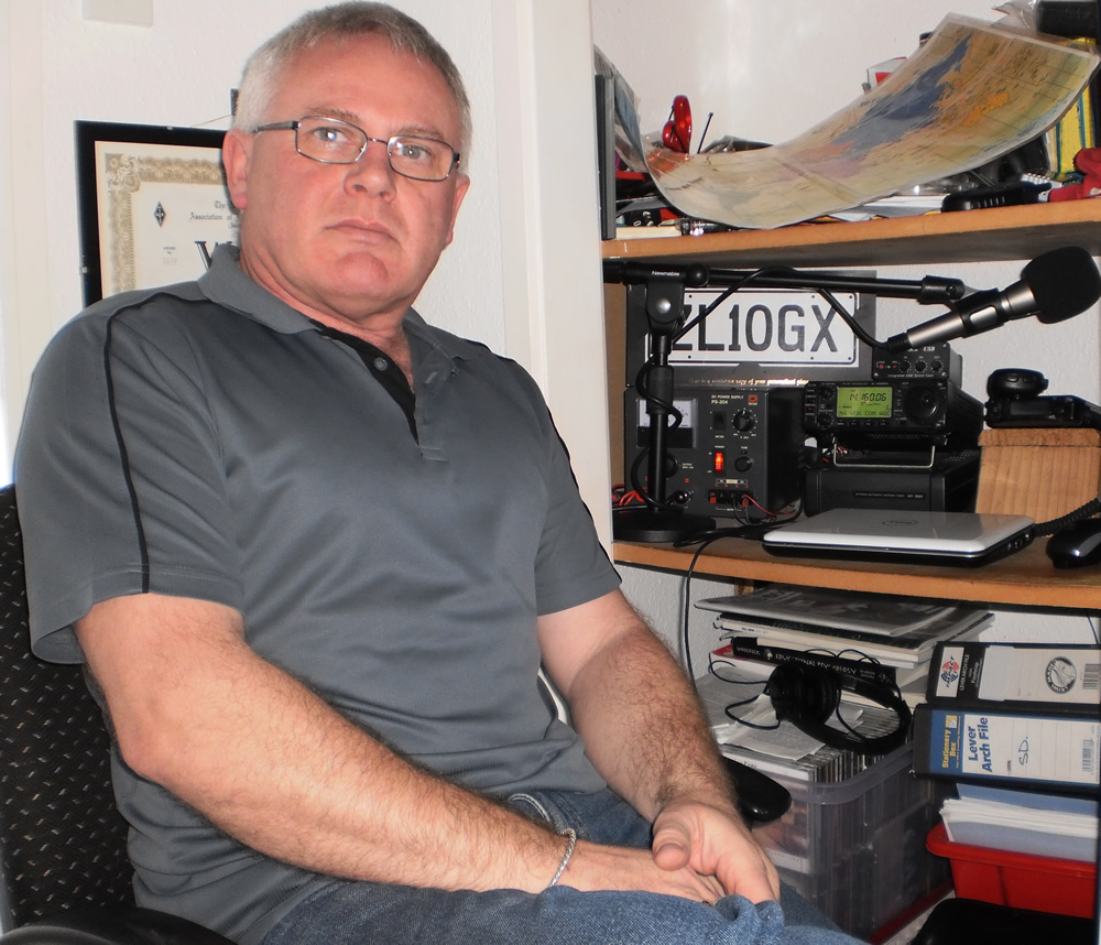
Ian ZL1OGX

Ian ZL1OGX

Having been licensed since 1987, just a new comer, I was issued the call GM1XOG. I worked mostly on 6Mtrs.  Being very close to the magical DXCC with 15w for a long time out of a Yaesu FT690r plus a small linear and a HB9CV for the antenna.  I managed the VUCC with relative ease after all there was a big lift what with the upcoming solar max.

After several years of playing on 50Mhz a few of my friends whom I had gone through the RAE with pushed me into doing the morse assessment, after passing I held on to the GM1XOG and got MM3XOG to go with it.

Coming to ZL land in 2003, I just brought the VHF/UHF handy, all the rest of the kit was due to be packed into the container and shipped off.  Once the gear arrived I set about getting a proper ZL call.  I applied to the MED with all my documents from the UK and asking for ZL1XOG, only to be told that the ‘X’ series was not issued, at that time, so they moved the ‘x’ to the rear and gave me ZL1OGX.

Once all sorted I set about getting a G5RV up and digging out the radio from the container stuff, the XYL was a bit miffed that the station was almost the first thing unpacked.

I have to say that operating from ZL has been interesting, you don’t quite have 50 – 60 DXCC countries on your door step, band conditions are totally different to what I experienced in GM land, it’s been a learning curve.

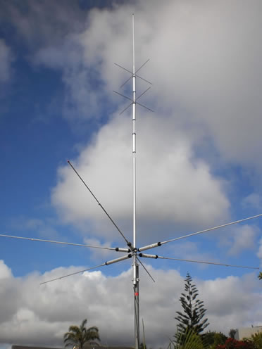
The Diamond CP-6 Multiband Vertical

The Diamond CP-6 Multiband Vertical

So today I still use the rig I brought over an Icom IC-706Mk2 with its ATU the AT-180 added a Heil mic to it.  The antenna has changed to a Diamond CP-6 vertical, the wife was complaining about the number of wires about the section.

Currently I’m sitting at 176 worked countries, yes not a lot but not too bad with 100w and a vertical and having to go to the office.  Also I’m playing about with digital modes at the moment, it’s fun working EU on 20-30w.zl1ogxQSL

Also in some of my spare time I look after the website of Branch 29 – NorthShore, www.qsl.net/zl1ab if you want a wee look.

QSL Direct, Bureau or LoTW

73 Ian, ZL1OGX


Things To Come – A Cautionary Tale

By LES MITCHELL, G3BHK* (From: Radcom Magazine 1984)

OUR LITTLE GROUP of local ex-service G3 types often meets for a drink in the snug of the old coaching inn down by the riverside. Discussion ranges far and wide, but as one might expect revolves mainly around our wartime experiences and, of course, amateur radio.

Recently someone pointed out that he had not heard Bill on the bands for some time. Bill had obtained his licence immediately after the war and had spent every available moment chasing dx or chatting to his friends on 3•5MHz. Since he retired a few years ago he had spent even more time on the air, and it was very unusual not to hear him working on some band whenever one listened. When we compared notes we suddenly realized that no-one had heard Bill’s signal for over six months. “You live nearest to him,” said Joe, “why don’t you drop in and see what has happened. Let’s hope he is not a silent key, but I am sure we would have heard something if he had passed on.”

A few days later I knocked at Bill’s door rather worried that I might be faced by a tearful and grieving widow. The door swung open to reveal Bill with a big grin on his face and looking fitter than I had ever seen him. Within a short time I was sitting in an armchair with a full glass in my hand and explaining why I had called.

“Well,” said Bill, “it is a long story. You see just after l retired a relative of mine died and left me a useful sum of money. As you know, all my rigs were getting quite old, so I jumped at the chance to completely renew all my station equipment. “First of all l purchased one of those Sky-Gain automatic aperiodic multi-band beams plus the computer controller. This array works on all bands and the computer turns the array to the maximum signal path without any effort on the part of the operator. I mounted this on my old 100 ft. tower and it was fantastic!

“Then I invested in the very latest transceiver, the Fuji Yama FJ 20,001 which covers all bands l•8MHz. to UHF with full legal power and no tuning whatsoever. To supplement this I also bought two computerized attachments-one which enables you to enter all the call prefixes of the countries you have worked already on each band, and then commands the transceiver to hunt each band in turn and only stops when it hears a new prefix. This unit also allows one to program automatic replies – callsign, signal reports, handle, location and requests to QSL etc. It had an additional program which made automatic calls to any of my friends’ callsigns it heard on 3•5 and 7MHz. l had to keep these replies updated with the latest news: you know the sort of thing-the car has gone wrong again. I have just mown the lawn, the rheumatism is painful, the income tax people have overcharged me again, etc.

“The second computer unit was the printout attachment which automatically printed the log entries and produced fully-completed QSL cards. So you see l could just leave the rig on 24h/day and it would work the rare dx and also chat to my mates on 3•5MHz without me going near it except to add more printout paper and blank QSL cards. Apart from a trip to the post office every day to post the QSLs, it left me time for decorating, car cleaning, gardening and after-meal naps. After it had been on the air continuously for about a month I discovered I had worked every dx station which existed, and even my friends on 3•5MHz were not replying to my calls-I expect they did not like the impersonal touch.

Then I suddenly realized that this new rig had utterly and completely destroyed my interest in amateur radio. Even the walk to the post office was boring me, and the parcel post costs were also becoming a strain. So l then made the decision that after nearly 40 years on the air it was time to give up my hobby, I sold the rig, and with the money bought the XYL all the labour saving gadgets I could find – a washing machine, a microwave oven, a food processor, a dishwasher etc. Now she has as much spare time as me so we have taken up golf. It’s very relaxing and gets us out in the fresh air. In fact we are spending more time together than we have done since we were courting!”

Bill and his XYL and l smiled at each other as she refilled the glasses. When I related this story to the others later there were sad faces all around. “But,” I added, “Bill did tell me that he intends to renew his licence every year, so perhaps at some time in the future we shall hear him on again.” But remembering just how those two smiled at each other I have my doubts.

Sign of things to come?

73, Lee ZL2AL (Reprinted from Radcom 1984)

HF Antennas & Feeder Lengths in Metres

This handy chart was developed by Gary, ZL2IFB. It is a very simple way of finding out what length of wire you need for your particular frequency. Thanks Gary!

Band CW SSB ¼ wave ¼ – 5% ¼ x 0.66 ½ wave ½ – 5% ½ x 0.66 Full wave F – 5% F + 10% F x 0.66
160m 1.825 41.07 39.01 27.38 82.13 78.03 54.76 164.27 156.06 180.70 109.51
1.850 40.51 38.49 27.01 81.02 76.97 54.02 162.05 153.95 178.25 108.03
80m 3.520 21.29 20.23 14.19 42.58 40.45 28.39 85.17 80.91 93.69 56.78
3.800 19.72 18.74 13.15 39.45 37.47 26.30 78.89 74.95 86.78 52.60
40m 7.025 10.67 10.14 7.11 21.34 20.27 14.23 42.68 40.54 46.94 28.45
7.100 10.56 10.03 7.04 21.11 20.06 14.07 42.22 40.11 46.45 28.15
30m 10.105 7.42 7.05 4.94 14.83 14.09 9.89 29.67 28.18 32.63 19.78
20m 14.020 5.35 5.08 3.56 10.69 10.16 7.13 21.38 20.31 23.52 14.26
14.250 5.26 5.00 3.51 10.52 9.99 7.01 21.04 19.99 23.14 14.03
17m 18.075 4.15 3.94 2.76 8.29 7.88 5.53 16.59 15.76 18.24 11.06
18.120 4.14 3.93 2.76 8.27 7.86 5.51 16.54 15.72 18.20 11.03
15m 21.020 3.57 3.39 2.38 7.13 6.77 4.75 14.26 13.55 15.69 9.51
21.250 3.53 3.35 2.35 7.05 6.70 4.70 14.11 13.40 15.52 9.41
12m 24.900 3.01 2.86 2.01 6.02 5.72 4.01 12.04 11.44 13.24 8.03
24.950 3.00 2.85 2.00 6.01 5.71 4.01 12.02 11.41 13.22 8.01
10m 28.025 2.67 2.54 1.78 5.35 5.08 3.57 10.70 10.16 11.77 7.13
28.500 2.63 2.50 1.75 5.26 5.00 3.51 10.52 9.99 11.57 7.01
6m 50.100 1.50 1.42 1.00 2.99 2.84 1.99 5.98 5.68 6.58 3.99
52.050 1.44 1.37 0.96 2.88 2.74 1.92 5.76 5.47 6.34 3.84

Where a full wave in metres = frequency in Hz divided by the speed of light (299,792,458 m/s)

Reduce dipoles by ~5% for end effects. Add 5-10% to full wave loops. Trim all antennas to resonance.

Lose one third physical length for velocity factor of typical coax. 73 de ZL2iFB

Cycle 24 Disastrous for Hams

The sun is currently in the peak year of its 11-year solar weather cycle scientists say.

This year’s solar maximum will probably be the weakest in 100 years and the next one could be even worse. The sun is currently at the maximum of Solar Cycle 24, but as this graph shows, there are far fewer sunspots during this peak than there have been in past cycles.

Cycle 24 in July 2013

Cycle 24 in July 2013

Solar Cycle 24 has been underway since 2011 and its peak was expected in 2013, but there have been fewer sunspots observed this year compared with the maximums of the last several cycles. The stage is set for an even smaller maximum during Cycle 25 around 2025.

A small Cycle 24 also fits the 100-year pattern of building and waning solar cycles as witnessed by scientists during the weak solar cycles at the beginning of the 19th and 20th centuries.

DX is always there. Even in the low times of the sunspot cycles. It’s just that you will have to be a bit more cunning to work it

I cannot remember a longer, more tedious cycle than this one and it’s the sixth one I have been in since 1958 although I did manage to catch the end of grand daddy of them all which started in 1948 and finished in 1952. The first big one for me was 1959-1961 when you could work the world on 10 metres day after day with low power. Sometimes the band was open 24 hours. This latest Cycle 24, except for a a few good bursts last year has been a big disappointment.

I will stress again that the DX is always there. Especially when a contest occurs, they all come out of the woodwork!

And that’s DXing folks!

73, Lee ZL2AL

Plasma TV RFI Cure by K9YC

Here are the main points.

1) If it IS the TV, SOMETHING connected to it is acting as a 160
meter transmitting antenna and radiating it strongly enough for your
receiving antennas to pick it up.

2) There may be more than two antennas. Prime candidates are whatever
that TV is using as a signal source (cable TV, satellite, roof
antenna), the power line, and even connections to the audio system.

3) Like any other 160 antenna, bigger makes a better transmitter, so
use your noggin in figuring out which of these antennas are most
likely to be the most effective long wire antennas.

4) Apply BIG ferrite chokes to those antennas (not your antennas, the
ones connected to the TV). What you are looking for is the greatest
possible impedance from the choke on the frequencies where you are
hearing trash. See the tutorial on my website to learn how to get
that high impedance. It includes graphs of lots of MEASURED data
contributed by another member of this list who did them in a very
good lab.

http://audiosystemsgroup.com/SAC0305Ferrites.pdf

While the tutorial is written for pro audio people, any decent RF guy
should be able to use it to understand, troubleshoot, and fix ham RFI
problems. I’m working on a tutorial dedicated to ham radio
applications.

5) You need Z on the order of several K Ohms to make a serious dent
in this trash. As the data shows, for 160, you are wasting your time
(and money) with anything less than 10-14 turns around a 2.4″ #31
toroid, or 7-8 turns through one of the biggest #31 clamp-ons.

6) Do NOT try to kill the noise by finding “a better earth
connection” for that system. Any noise that you shove into that
ground wire will radiate, just like any other antenna carrying RF
current.

7) If you are going to put a commercial AC line filter on the set,
make sure that you have the shortest possible connection between the
filter and the set, ESPECIALLY for the green wire. See #6 above.

8) 12-14 turns of twisted pair like THHN stranded around that #31
2.4″ toroid makes a very good common mode choke for 160-40 meters.
Run only “hot” and neutral through the toroid, carry the green wire
around it. Put an RF cap of at least 0.33 uF between line and neutral
on the power source side of the choke. This cap will form a
differential mode filter with the imbalance in the inductance of the
choke. It must be rated for the AC line voltage. The wire in this
choke doesn’t need to be very big — the vast majority of standard
IEC power cords are #18, even those that look a lot beefier.

9) Do NOT add capacitance between hot or neutral and the green wire.
In addition to #6 above, doing so would create more leakage current
at power frequencies than is permitted under safety codes.

73, Jim Brown K9YC

Decibels Made Easy

Decibels Made Easy (Without Logarithms)by Bruce Spratling, Jr.

Suppose your station has a transmitter that puts out 50 watts of power, a feed line that loses all but 40% of the power, a duplexer that loses half the power, and an antenna that produces enough gain to make the signal 4 times as strong as a dipole antenna. To find the effective radiated power of your station you need to multiply 50 watts times .4 (feed line loss) times .5 (duplexer loss) times 4 (antenna gain) = 40 watts.

Rather than multiply all these factors together, someone decided it would be good to represent them in a way that allows us to add them. An increase of a factor of 10 is defined to be a 10 decibel increase. Decibels are abbreviated dB. Two 10dB increases produces a 20dB increase, because we add decibel increases.

Two increases by a factor of 10 results in an increase of 10 X 10 = 100; therefore 20dB = 100. Three 10dB increases is 30dB, which is 10 X 10 X 10 = 1000.

Because we want to be able to add the dB increases, 0 dB is a factor of 1. Multiplying something by 1 does not change it, just as adding 0 to something results in no change.
Decibels       0         10         20             30
Factor           1         10        100          1000
It’s easy to figure out the meaning of 10, 20, 30, 40… dB, but how about decibels less than 10? Note that if we multiply 2 by itself 10 times, it generates the following: 2, 4, 8, 16, 32, 64, 128, 256, 512, 1024.

2 times itself 10 times is 1024, which is slightly more than 1000, which is 30dB. 3 added to itself 10 times is 30, and 30dB is a factor of 1000. Therefore, 3dB represents a factor of (approximately) 2.

Another way to derive that 3dB represents a factor of 2 is this: If we add 3dB to itself 3 times we get 9dB, which is less than, but close to, 10dB. If we multiply 2 times itself 3 times we get 2X2X2=8, which is close to, but less than 10. This is good because 9dB should be less than 10 (since 10 dB is 10). We have to multiply 8 by 5/4 to equal 10, and we have to add 1dB to 9dB to equal 10dB. Having 3dB = 2 will work if 1dB = 5/4.

Does 1 dB represent a factor of 5/4? If we apply 1dB 3 times, we’ll have 3dB, which = 2. (5/4)X(5/4)X(5/4) = 125/64, which is close to 2. Therefore, a 3dB increase represents a 2 times increase, and 1 dB represents an increase of 1.25.
6dB = 3dB + 3dB. A 3dB increase is a factor of 2, so 6dB = 2 X 2 = 4. Similarly, 9 dB = 2 X 2 X 2 = 8.

So far we have:
Decibels     0     1     2     3     4     5     6     7     8     9     10
Factor         1  1.25          2                   4            8            10
Let’s consider negative decibels. -1dB changes 10dB to 9dB, which changes 10 to 8. Therefore, -1 dB is .8, because .8 times 10 = 8.
To find 8dB, think of 8dB as 9dB – 1dB = 8 X .8 = 6.4. To find 5dB, think of 5dB as 6dB – 1dB = 4 times .8 = 3.2. Note that 5dB + 5dB = 10dB = 10. Using 5dB = 3.2: 3.2 X 3.2 = 10.24, which is about 10. To find 2dB, use 2dB = 3dB – 1dB = 2 X .8 = 1.6

Decibels                    0       1        2       3       4        5             6         7         8         9       10
Estimated Factor     1     1.25     1.6     2     2.5     3.2           4         5         6.4       8       10
Actual Value              1     1.26     1.58 1.99 2.51    3.16     3.985    5.01     6.31    7.94    10
% Error                   .714   -.944    -.236        .475  .178      -.473      .237    -1.41  -.708     0
You’ll notice from the chart that the results are all within 1.5%.

To summarize the system:
Realize that           3dB = 2,           so 6dB = 4,           and 9dB = 8.
You know the value for 3, 6, and 9dB (2, 4, 8).
To find 2, 5, or 8dB (1 less than 3dB, 6dB, or 9dB), use -1dB = .8.
If you want to know 4 or 7dB (1 more than 3dB or 6dB), use 1dB = 1.25.
To find fractions of 1dB, realize that 1dB represents a 25% increase, so .1dB is a 2.5% increase, .2dB is a 5% increase, .4dB is a 10% increase. (This interpolation method isn’t exact, but it’s fairly close when dealing with such small values).
You can carry this further for hundredths of a decibel. .01dB is one tenth of .1dB. .1dB is 2.5%, so .01dB is .25%. .04 dB is 1%.

An example: Suppose an antenna has a gain of 17.68 dB. How much increase is this? Note that 17.68 = 10 + 7 + .68. A 10 dB increase is a factor of 10. A 7 dB increase is a factor of 5. Therefore, a 17 dB increase is a factor of 10 X 5 = 50. .6 dB is 15%, .08 dB is 2%, so .68 dB is about 17%. 50 X 1.17 = 58.5, so the antenna increases the signal strength by a factor of 58.5, the signal is 58.5 times as strong (the exact value is 58.61).
Another example: An antenna’s signal is 25 times stronger than a dipole antenna. How many decibels is this?

This is actually quite easy. A 10 dB increase is a factor of 10. Because 25 = 10 X 2.5, we still have an increase of 2.5 to account for. An increase of 2.5 is 4 dB, so the total increase = 10 dB + 4 dB = 14 dB (the exact value is 13.98 dB).
Suppose we have an increase of a factor of 30. How many decibels is this? 30 = 10 X 3. To multiply by 10 requires 10dB. But, we need to add the decibels needed to multiply by 3. 4dB is 2.5, but we need 20% more (3 is 20% more than 2.5). 20% is about .8dB, so 30 = 14.8dB (the exact value is 14.77).

Well, that’s my system for decibels, and as promised, I didn’t mention logarithms!

Dead Electrical Dudes No. 9 – DeForest

Dead Electrical Dudes No. 9

This Month’s Stiff: Dr. Lee DeForest
Entered Mortal coil: 26 August 1873
Assumed Room Temperature: 30 June 1961

Dr. Lee DeForest

Dr. Lee DeForest

Dr. Lee Deforest
Father of Radio, Grandfather of Television
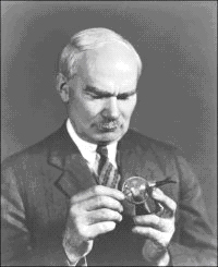
“How does this blamed thingy work?”

Okay kids, stop laughing! If you’re not familiar with the history surrounding Dr. Deforest, then rest assured that the monikers below his mugshot were not coined by me. Lee used these very terms to describe himself in his later years as he struggled to remain in the limelight and create some sort of lasting legacy. It was only by the slimmest of margins that the above photograph, or one similar to it, does not bear a serial number on the bottom denoting the booking of someone freshly arrested. To be honest, I had a difficult time remaining objective while researching this month’s Dude, as Major Armstrong is one of my personal heroes. So let’s quit fooling ourselves and drop any pretense of being impartial and fair!

Lee’s colorful life makes for interesting reading. From an early age, Deforest was determined to be successful at any cost, and his dream was to amass a large fortune. In the course of his life he made several fortunes. Lee lost several as well; all due to poor business sense, unwise choices for partners, and impressive legal fees accrued from defending himself from patent infringement and suing others. When Lee died in 1961, he only had $1,250 in his bank account. Here’s a few of the high and low points of Lee’s life:

The Spade Detector:
In 1903, Deforest learned of Reginald Fessenden’s new electrolytic detector for use in radio receivers during a casual visit to the fellow inventor’s laboratory. Lee copied Fessenden’s circuit, modified it slightly, and renamed it the Spade Detector. Fessenden discovered this infringement, sued Deforest, and won. Fessenden was awarded damages.
Invention of the Vacuum Tube Triode:
Deforest modified the diode detector tube in 1906 by adding a third element, which was termed the grid. Amplification of signals many times was now possible. However, the triode tube, or “Audion” as he called it, did not work very well. Additionally, no one understood how it worked, especially Lee.

It took the genius of Armstrong to unlock the power of this new device via the principal of the feedback circuit. Lee resented the younger inventor, and proceeded to sue Armstrong over this perceived challenge. What followed was perhaps the longest patent battle in history, from 1914 to 1934, with Deforest eventually winning the rights to regeneration. While on the stand, Deforest could not describe how the circuit worked in coherent terms. Despite the legal outcome, the scientific community did not recognize the ruling of the Supreme Court, as they believed Deforest had stolen the invention from its rightful owner. After all was said and done, the invention of the vacuum tube triode is considered to be one of the fundamental inventions making modern radio communications possible.

Accused in 1912:
Deforest and his partners Smith, Burlingame, and lawyer Samuel Darby, were accused of four counts of mail fraud and other wrongdoings by stockholders in their management of the Radio Telegraph and Telephone Company. Perspective stockholders were induced to buy into the new company via demonstrations of radio communications with Paris, France. It was later learned that the demonstrations were conducted from a hidden transmitter only blocks away. Smith and Burlingame were found guilty. Upon hearing of his acquittal on January 1, 1914, right after New Year’s, Deforest collapsed in his lawyer’s arms. During his life, Deforest started well over 30 companies, and helped drive each into bankruptcy.

Phonofilm:
Deforest dabbled in movie technology and came up with a method of recording sound on motion picture film in 1920. The audio information was recorded on a vertical strip on the edge. Sound was reproduced by directing a light beam through the strip, where it was detected by a photocell. The variations in the light’s intensity were converted to sound energy, and amplified via the usual methods. This technology is still in use today in various forms. Lee received an honorary Oscar for his invention in 1959.

Four Marriages:
Good ole’ Lee really had a way with the ladies! His first wife was Lucille Sheardown, whom he married in 1906, and newspapers reported that the inventor had won her hand by tapping out love messages to her in Morse Code. The marriage was never consummated, and the couple divorced the same year. In 1907, he married Nora Blatch, who was probably every bit as smart as Lee. Deforest refused to accept her as a partner in his research and business dealings, and she subsequently divorced him after bearing a child. In 1912, Lee wed pretty opera singer Mary Mayo, and stayed with her for 15 years, despite her being an alcoholic. They had two children together, but one died at birth. Finally, Deforest married 21 year old actress Marie Masquini in 1930. Marie stayed with the crotchety old inventor until his death. She apparently was the love of his life and a good woman, tending to Lee tenderly in his final days.

Deforest thought of himself as the Father of Radio, and wrote an autobiography under the same moniker in 1949. As an experiment, he had a letter mailed to Hollywood, California, where he resided, with only the words “Father of Radio” on the envelope. The letter was returned to the sender with “addressee unknown” stamped on it. During an episode of “This is Your Life”, Lee was also hailed as the “Grandfather of Television”. Lee also tried unsucessfully to convince Marie to write a book about him: the prospective title would have been “I Married a Genius”. Talk about gall!
Deforest’s life story is replete with tales of controversy, envy, avarice, brilliance, culture, and romance. The reader is encouraged to research further. I apologize if this particular essay ran a little on the long side.

73, Philip Neidlinger, PE KA4KOE

References and Tidbits:
Empire of the Air: The Men Who Made Radio, Tom Lewis

The Complete Lee Deforest Web Page. URL http://leedeforest.org

Biography of Deforest, PBS. URL http://www.pbs.org/transistor/album1/addlbios/deforest.html


Dead Electrical Dudes No. 8 – Morse

Dead Electrical Dudes No. 8 by Philip Neidlinger (KA4KOE)

This Month’s Stiff: Samuel Finley Breese Morse
Entered Mortal coil: 27 April 1791
Assumed Room Temperature: 2 April 1872Morse1

In Memoriam: Sam Morse
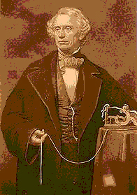
I decided to do a short essay on Sam Morse given the recent turn of events. I was all set to write you good folks an article on Ampere this time, but alas, it was not to be. Just think, if Sam’s life had turned out a little bit differently, there would not be a system of communications referred to as “Morse Code”, which is a misnomer anyway. The system of dots and dashes may have been invented by someone else and called Johnny Code, or Algernon’s Code, or Fred’s Code, or Old Code (I love rhymes). In my opinion, the code was so simple that it was bound to have devised by some other lad or lass, and we’d have their sepia portrait at the top of this page instead. I like this picture. Instead of holding a book like our dearly departed Count Volta, Sam is holding a telegraph tape. Why isn’t he looking at the tape? Perhaps he is gazing off in the distance contemplating the future. Who knows? Whimsical speculation on your part is highly encouraged in the maelstrom of postings this article is sure to set off. Who was Morse, the man?

Samuel Morse was born in Charleston, Massachusetts, near Boston. Like many an extremely bright youth, Sam didn’t appear to have any direction in his college studies. He was basically a good kid, and wasn’t prone to wild partying, like our friend Ohm. I suspect that some of his father Jebidiah’s inevitable lectures, while Sam sat on his knee, on morality had something to do with it, as the old man was a preacher. As it was, his parents were not happy with the young man’s penchant for painting. Actually, Sam was quite good at it, and was highly respected in his skills. During his college years, he was fascinated by lectures he attended on the groundbreaking subject of electricity. As chance would have it, in 1832 Sam heard about a new invention, the electromagnet, while sailing back to the good ole’ United States after conducting art studies in Europe. A “Eureka” moment occurred, as Sam believed that the invention could be developed into a means of communication. Perchance if Sam hadn’t overheard that conversation, he would’ve died a poor artist.
The idea of an electric “telegraph”, however, was not new. A competing system utilized a system of many wires and a needle pointer mechanism. The needle would rotate to the letter “a” for instance, when the associated inputs were set. However, Morse’s system utilized only a minimal number of wires. A sequence of long and short circuit closures was assigned for each letter and number; a code, if you will. After further development with the assistance of a couple of partners, Morse applied for a patent in 1837. The new invention caught on rapidly. By 1843, with federal funding, telegraph lines were installed between Boston and Washington, DC. In 1844, his now famous message, “What hath God Wrought”, was transmitted by Morse himself between the two cities.

Sam’s system used an electrically-driven needle to mark the long and short dashes on a moving strip of paper, where they could be decoded. However, much to Morse’s incredulity, telegraph operators soon gained enough skill to the point that they could translate the sounds of the electromagnet clicking directly in their heads, and write the letters down as they were sounded out. A common misconception is that Morse’s code is the same code that is currently in use today by hams worldwide. This is not true. Although they share similar characters, there are significant differences. The International Morse Code retains his name to honor the inventor.

In his later years, Morse was married a second time in 1848 to a cousin and begat more children in addition to those begat from his first marriage. He was quite the philanthropist. Sam gave generously to the art programs at Yale and Vassar Universities, and others, and helped out young artists whenever he could. The wealthy inventor died in pneumonia in 1872 while in New York City.

Philip Neidlinger, PE KA4KOE

Dead Electrical Dudes No. 7 – Hertz

Dead Electrical Dudes No. 7 by Philip Neidlinger, P.E. KA4KOE

This Month’s Stiff: Heinrich Rudolph Hertz
Entered Mortal coil: 22 February 1857
Assumed Room Temperature: 1 January 1894

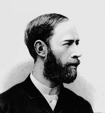
Heinrich Rudolph Hertz

Heinrich Rudolph Hertz

Heinrich Rudolph Hertz
Perhaps the burning question on my mind is why did a lot of the early electrical pioneers sport such interesting beards? Put a rifle in the picture and I can just imagine Heiny walking out of the piney woods after distilling a few hundred gallons of ‘shine.
As you may recall, the existence of electromagnetic waves was predicted mathematically by James Clerk Maxwell and was discussed in the first of this series of irreverent articles. Mathematicians, physicists, and scientists will, on occasion, develop elegant formulae that don’t amount to much except to illustrate some arcane concept with no practical application. However, such was not the case in this particular instance. Heiny took Maxwell’s headache-inducing formulae and proved that they did, in fact, describe a natural phenomenon.

Hertz was born in Hamburg, Germany. At an early age it became apparent that the boy was scientifically inclined. Young Heiny enjoyed building instruments of various types in the family workshop. Hertz began his formal education in 1877 at the University of Munich where he studied engineering. Only a year later, Hertz abandoned engineering (blasphemy!) and began his study of natural sciences at the University of Berlin, studying under Helmholtz and Kirchoff (sound familiar?) where he earned his Ph.D, with magna cum laude honors. His mom must have been a very proud woman! A topic of intense interest in the scientific community at the time was determining whether or not Maxwell’s equations were valid. In 1883, the young scientist also directed his attention to this course of research.

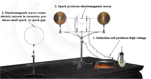
In 1887, Hertz conducted his now famous experiment in which two antennas were placed a few feet apart. The first part of the device consisted of essentially a crude spark gap transmitter connected to the first antenna. The receiving antenna was a loop with a couple of electrodes on the wire ends placed very close together. Hertz activated the transmitter and it generated sparks. Sparks were also seen leaping across the electrode gap at the receiving antenna. Further experiments were conducted in which it was determined that the invisible waves could be reflected and refracted in a manner similar to that of light waves, and finally that light waves were also electromagnetic in nature. Maxwell’s theories were finally vindicated eight years after his death! Hertz’s findings were published in 1892 in his book, Untersuchungen Ueber Die Ausbreitung Der Elektrischen Kraft (Investigations on the Propagation of Electric Energy).

Hertz Apparatus

Hertz Apparatus

Mockup of Hertz’s Classic Experiment
Unfortunately, Hertz died young at the age of 37 from blood poisoning. Associates and friends remember the professor as amiable and modest, and people seemed to be naturally attracted to him. In his honor, the unit of frequency measurement, the Hertz, was named after him.

A young Italian boy read about Hertz’s experiments and it galvanized his attention. I’ll give you three guesses who that boy was!

Philip Neidlinger, P.E. KA4KOE

References: The Spark Museum, http://www.sparkmuseum.com/

Empire of The Air DVD

Empire of the Air DVD – A film by Ken Burns
Narrated by Jason Robards. Running time 120 minutes – Colour/B&W
A PBS Video ISBN: 0-7806-4057-8
Empire of The Air

Reviewed by Lee Jennings ZL2AL

For 50 years radio dominated the airwaves and the American consciousness as the first “mass medium” This film by Ken Burns examines the lives of three extraordinary men who shared the primary responsibility for the invention of radio and it’s early success, and whose genius, friendship, rivalry and enmity interacted in tragic ways. It is the story of Lee de Forest, a clergyman’s son who invented the “audion” tube; Edwin Howard Armstrong, a brilliant withdrawn inventor who invented, regeneration, oscillation, the the superhetrodyne receiver and finally the FM:technology we know today and David Sarnoff, a hard driving Russian immigrant who created the most powerful communications company on earth.

The video portrays these three almost dysfunctional pioneers who plotted, schemed and invented the technology which changed the communications of the world. It also tells the story of giant egos, jealousy and epic courtroom battles that consumed them to the point of multiple marriages and divorces, bankruptcy and suicide. There were of course many other inventors of radio around the world. Although this is a story from an American perspective it doesn’t diminish the drama and intrigue of the era. If you thought that Stephen Job of Apple and Bill Gates of Microsoft had a dustup you can appreciate the acrimony of these pioneers as they waged legal war with each other over their inventions and patents. While they spent time in the courtroom, David Sarnoff bought the licences for their inventions to make a fortune and become the most powerful media man in the USA owning both RCA and the NBC Broadcasting network. Incidentally, David Sarnoff was also an amateur radio operator.

The wonderful black and white still photography and colour clips of the early television era paint a vivid picture of the age. Interviews with prominent family members and early broadcasters fill in the backgrounds of these men. I was amazed to learn that Lee de Forest’s dream of broadcasting speech and music to the masses was pinched by the Canadian Regenold Fessenden who beat him to it by one year. Fessendon had General Electric build him a steam-powered alternator with enough poles to produce a carrier of about 80 KHZ. His modulator was the carbon microphone element from a telephone in series with the field coil. It is thought that when his steam turbine was running at maximum, his generator may have produced as much as 100 KHZ (UHF). On Christmas Eve of 1906,

Fessendon tried out the setup on an island just off the coast of Virginia. He and a friend spoke Christmas greetings to anybody who was listening, played a violin, and frequently gave out an address to which people could write if they heard the broadcast. It probably sounded terrible, but they got cards and letters from people all up and down the East Coast. It is said that people used to listening to the static crashes and buzzing CW signals from spark transmitters thought they were losing their senses when voices and music began to be heard. There were a few steam-powered RF alternators built in the world, but vacuum tubes were discovered around 1907 or so and electronics as we know it was born.

One two minute film clip showed about 12 well dressed gentlemen with bow ties in front a microphone creating the live sound effects for a “western” drama. Absolutely hilarious! Amateur radio is not mentioned in detail but the magnificent towers and radio antennas that were constructed back in those days are a wonder to behold. Marconi’s place in radio history is preserved and the sound and power of a fully operational rotary spark transmitter is awesome! Cutting edge technology between about 1885 and 1920 was to put a tuning coil on the output of the spark gap and to put the gap in to a chamber filled with hydrogen or some other substance and devoid of air so that a hotter spark could be made. Sometimes, the operator got a little too much air in the chamber by accident and the hydrogen would ignite, blowing the whole thing sky high, but that was just an occupational hazard of keeping in touch by wireless in those days.

I watched spellbound for two hours as the drama unfolded. The DVD from Amazon www.amazon.com at $18.00 USD over the internet and the shipping time is about 6 days from the USA. It was originally produced for the PBS (Public Broadcasting System) in the USA for running as a two hour documentary over a few weeks. It is well worth purchasing and would make an excellent video for club use.