IBM 704 Scientific Computer

The IBM 704 Scientific Computer

IBM 704 LJ at Console

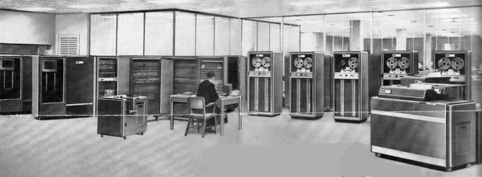
Magnetic Core Stacks at the Left, Mainframe in the Centre.
727 Tape Drives with the 407 Line Printer at the right

Sometimes truth is stranger than fiction. After leaving college in Toronto I went to work for IBM Canada as an engineer. After a 6 months course at the Don Mills IBM plant in Toronto I left for Ottawa for a 1 year stint servicing  the punched card accounting machines that analysed and crunched the data for the 1958 Canadian Census. Punched cards generated big money for IBM. It was the dawn of the computer era and after another few  months of training during 1959 I was assigned to the new IBM 704 scientific computer based at the A V Roe plant on the outskirts of Toronto along with 2 other technicians. The A.V. Roe Aircraft Company of Canada was building the Avro Arrow and the 704 was to be used for design work. The aircraft was a revolutionary jet interceptor, designed and built by Canadians. The delta winged Arrow was a plane of firsts: fly by wire, computer control, and integral missile system and capable of MACH 2+. The COLD WAR with the Soviet block was raging.

That’s me at the console in the photograph above.  I was 23 at the time.

IBM manufactured and sold 136 704s. This one was the only one that ever made it to Canada. The usual method of input to the system was magnetic tape, but entry could also be gained from punched cards through the card reader or from the operator’s console, if special instructions were required. All information, whether part of the data to be processed or part of the program of instructions, started out on punched cards. Then, it either could be converted directly to magnetic tape before being read into the system, or it could be read directly.

At the start of each procedure, the program of instructions was read into the memory from tape or cards and was stored there for use with each record processed. Usually the records to be processed would already have been converted from punched cards to tape or would be on a tape that was the output of an earlier processing operation.

The results of the processing were either produced on a line printer, on a magnetic tape, or on punched cards. If the operator did not want to tie up the entire system while the relatively slow printing or punching was accomplished, he or she could produce an output tape, then connect a tape unit directly to the printer or card punch and print out or punch the results without using the principal components of the system.

It had some massive computing power for it’s time which included 2 x 512 k magnetic core memory stacks, 6 high speed tape readers, punched card input reader and the huge mechanical line form printer on the right of the photo. The tape handlers at the back in the picture were IBM 727s, among the first drives using vacuum columns and tapes made from plastic which was coated with an iron oxide for magnetic storage. These tape drives and, more importantly, the tapes themselves stimulated the acceptance of half-inch-wide, 7-track tape, with recording densities of 200 cpi, and speeds of approximately 60 inches per second (ips) as an industry standard. Additional capacities were added over the years: 556, and 800 cpi, and speeds of 120 ips or more. Each 36-bit computer instruction contained 1 or 2 address fields of 15 bits, so that the full 32K, 36-bit word memory could be addressed directly. The two fields were called decrement (an index) and address, and those names live on in the LISP commands CDR and CAR.

The main console is shown below.

The 704 Main Console

The IBM 704 became the dominant vacuum-tube logic computer in the late 1950’s. A 32K, 36-bit word memory was the largest available. The console is shown below and you could read what was in the memory stacks from the neon bulbs above. You  could also input a binary word via the switches below. It was programmed in Fortran language and had a 36 bit binary word as it’s data on the wire buses. Each 36-bit computer instruction contained 1 or 2 address fields of 15 bits, so that the full 32K, 36-bit word memory could be addressed directly. The two fields were called decrement (an index) and address, and those names live on in the LISP commands CDR and CAR.

IBM stated that the device was capable of executing up to 40,000 instructions per second.

The programming languages FORTRAN and LISP were first developed for the 704, as was MUSIC, the first computer music program by Max Mathews.

In 1962 physicist John Larry Kelly, Jr created one of the most famous moments in the history of Bell Labs by using an IBM 704 computer to synthesize speech. Kelly’s voice recorder synthesizer vocoder recreated the song Daisy Bell, with musical accompaniment from Max MathewsArthur C. Clarke of 2001: A Space Odyssey fame was coincidentally visiting friend and colleague John Pierce at the Bell Labs Murray Hill facility at the time of this remarkable speech synthesis demonstration and was so impressed that he used it in the climactic scene of his novel and screenplay for 2001: A Space Odyssey,[2] where the HAL 9000 computer sings the same song.

64K Magnetic core memory stacks using physical ferrite “doughnuts” about 10mm diameter which had a X and Y wire pass thru them and a “sense” wire wrapped around the ferrite which would sense the magnetic “flip” caused by the X and Y currents. The ferrite doughnut would then represent a digital 1 or a 0

The magnetic but because of the cost of memory 8K and 16K systems were common. It was the first IBM machine to use core memory. The memory cycle time was 12 microseconds and an integer addition in its registers of 36 bits required two cycles, one for the instruction fetch and on for the data fetch. Floating point operations required on the order of 10 such cycles.

During their tenure, memory capacity grew as IBM learned how to make core memory. Initially, the 704 had 4K, then 8K then 32K words. A word was 36 bits. The 704 was a nightmare to work on. It had 4000 tubes and an 8 Mhz clock with 117 miles of wiring. The tubes were mostly 12AT7s on a “pluggable unit” with 8 tubes on it.

The 8 tube Pluggable unit with “real” resistors and capacitors.
This unit represented 1 “bit” in a 36 bit word in one register

The 4000 tubes ran on on +150 Volt and -150 Volt power supplies with 12 VAC for the tube filaments. Needless to say the machine generated enormous amounts of heat and required 32 tons of air conditioning to keep it a constant temperature. As the engineering technicians, it was our job to keep the machine running. We used to bring up power and get the machine up to temperature each morning at 7 Am and then run a “Round Robin” program which checked out every possible function in Fortran. While it was doing it’s run, our job was to vary the DC voltages until it failed and note where it failed. We then had to return the  machine to normal operation and have it ready for an 8 Am customer start. During the day, we poured over manuals and diagrams trying to figure out which tube (or tubes) was failing to cause the problem. At 5 Pm or the next morning we would replace a pluggable unit and check to see whether the problem went away. When it didn’t go away and got worse each morning we all knew that panic was not far away and IBM management took a dim view of the machine not working as it cost them a lot of revenue every hour it was off line.

I was “married” to this 704 computer and was on call any time if required, along with 2 other technicians from 1959 to 1962. When AV Roe in Malton Ontario closed down the Avro Arrow production because of the decision to “can” the Arrow by the Canadian Diefenbaker government we dismantled the whole machine and re-assembled it at the IBM Data Processing Center on Eglinton Avenue in Toronto where we set it up again. It then operated as a data cruncher for an oil company and a University and other commercial customers. I understood that IBM rented it out at thousands of dollars an hour. Demands for computing were growing rapidly and the world was well over tubes and into transistors. Solid state was the word! I started to work on solid state equipment and then decided to leave IBM after 7 years to work for Canadian Motorola. I didn’t realize it at the time, but it was the greatest privilege to be able to be there at the dawn of the computer revolution. Yes, Bill Gates and Steve Jobs did some cool stuff in the 1980s and the urban myth is that it was the beginning. It wasn’t!

IBM was the beginning and for 20 years they dominated the industry with the 700 series, 650s, 305 Ramacs and other commercial computers. Sadly, they never saw Bill Gates, Steve Jobs and others of their kind coming and IBM lost it’s whole business base to the silicon valley upstarts. The IBM empire slowly crumbled and changed. It became a mere shadow of it’s former self. Interestingly, both Microsoft and Apple are trying to stay on top today as IBM did back then. I wonder if in 30 years time I would be able to write the same story about corporate arrogance and incompetence. In any case. it was the end of an amazing era. Working for IBM was a privilege. It was a time in history and a chance for me that will never happen again. I am still amazed that I was part of that continuing story of the computers.

Leith Jennings

Choosing Your First Radio

Choosing Your First Radio by – Chris Levin, KB7YOU 

1 Introduction

Ham radio is an exciting hobby – and there is a lot more to it than just talking on the radio.

Amateur radio provides a framework that supports a wide variety of interests. With amateur radio as a resource and guide you can experiment with digital communications and RF/Internet gateways, you can design and build electronic devices and talk to stations in outer space.

You can study propagation and atmospheric conditions or listen to interstellar signals created by the explosion of stars and much more.

Of course, communications is an important part of the amateur radio world. Meeting new people around town and around the world is tremendous fun.

Whatever your interests and goals, amateur radio can provide value to your endeavors.

The very versatility that makes ham radio so interesting can also cause problems. As a new ham or even as an experienced operator trying out a new aspect of the hobby, the huge amount of information available can be difficult to sort through. The Internet can be a valuable tool but with so many people giving conflicting advice, how do you know what’s right? That’s where this paper comes in. My goal is to give the new ham some basic, general information on radio types, their pros and cons and the ways that they can be used.

The information in these pages is based on my first hand experience. I don’t write about things I have no skill or experience with. By following these rules I can ensure good accuracy in the information I present.

I hope that you enjoy reading this document and that it helps you with your radio purchase. If you have questions, comments or corrections I would enjoy hearing from you.

2 Radio Types

2.1 Terms you need to know:

  • DC to Daylight – Refers to the new breed of radios that cover the HF (1.8MHz – 30MHz + 50MHz to 54MHz), VHF (144 MHz – 148 MHz) and UHF (420 MHz – 450 MHz) amateur bands. These are all mode radios and are available in a variety of form factors and feature sets.
  • All Mode – A term used to describe radios that support CW, SSB, AM, FM and various digital communication modes. Most modern HF radios and some VHF/UHF radios are all mode.
  • Dual Band – Generally refers to a radio that covers the 2 meter and 70 centimeter amateur bands.
  • HF – The 160 meter to 6 meter amateur bands.
  • VHF –The 2 meter amateur band.
  • UHF – The 70 centimeter amateur band.

Choosing a first radio is one of the most important decisions you will make – and one of the toughest. The right radio for you will depend on what you want to do now and in the future. It can be hard sorting through all the advice. To get you started I have listed each of the common radio types and some reasons to consider each.

2.2 Mobile 2 Meter and Dual Band Radios
The mobile 2m or dual band radio is the workhorse of local communications. These radios are most commonly used for communications via local repeaters and for short haul simplex communications. Most of these radios will also let you do PACKET or APRS communication with the addition of software and hardware. Some dual band mobile radios are also suitable for basic satellite communications. The majority of mobile radios are FM only and the most common bands they support are 2m and 70cm.

There are many radios available in this category. Prices range from under $200 for a basic 2m mobile up to $500 for models with built in PACKET modems and APRS software.

Things to consider:

  • If you live in an area with an active ham community chances are good that there is a lot of activity on the 2m and 70cm FM bands. One of these radios will give you lots of opportunities to communicate.
  • If you have a Technician license and plan on waiting a while to upgrade then your HF choices are very limited. A 2m, 70cm or dual band radio is an excellent choice for day to day communications.
  • If you are interested in PACKET or APRS then you need a 2m FM radio. A basic mobile rig or one of the more sophisticated rigs with a built-in PACKET modem is a must for these modes.
  • If you drive a lot or like to take road trips the mobile dual band radio is an excellent choice. In remote areas, the relatively high power output of these radios (usually 25 to 75 watts) will allow you to make contacts over distances of 20 to 50 miles.

Advantages:

  • High output power – These radios have power outputs ranging from a low of 20 watts up to 100 watts for some models.
  • Flexible – You can use these mobile radios in your car or your house (with the addition of a deep cycle battery and/or power supply). They also work with a wide variety of antennas allowing you to choose an antenna that suits your needs.
  • Feature rich – The larger form factor of these radios makes it simple for manufacturers to add extra features. The larger size also means that buttons and displays are larger and easier to use. You can purchase mobile radios with built in TNC’s (PACKET modems), cross band repeaters, general purpose scanners and other features.

Disadvantages:

  • Power requirements are higher than for handhelds. Most mobile radios are not going to be suitable for QRP or camping applications because of the large batteries required.
  • Limited modes and bands – These radios only work on the 2m and 70cm bands (some also cover 220MHz, 6m and 10m). Most of these radios only support FM communications.
  • External power supplies or batteries are needed for home use.

2.3 The DC to Daylight Radio

The “do it all” HF/6m/2m/70cm (and even higher!) radios are relatively new to the market. Often referred to as “shack in a box” radios they can be a great way to explore all of the common modes and bands available to the curious ham.

So why should you consider one of these radios? There are several reasons. First, they give you a little bit of everything – HF, 2m SSB, local repeaters and more. They are also great space savers if you don’t have room for multiple radios. If and when you decide to add a specialized radio to your setup or if you decide to buy a better performing “built to task” rig, your DC to Daylight radio will make a fine secondary rig. In many cases you can use it in conjunction with your other radio (especially if they are from the same manufacturer) to facilitate things like full duplex satellite operations. These radios will serve your needs as your license privileges grow and as your interests change.

Advantages:

  • Ready to go as you upgrade your license.
  • Space saving.
  • Many DC to Daylight rigs have rich feature sets and support things like satellite communications, packet cluster tuning and other digital modes and computer control.
  • Good features per dollar. These rigs give you a lot of “bang” for the buck.
  • Available in mobile and base station sizes and recently in portable/backpack sizes.

Disadvantages

  • Can be complex to operate with many menus and options.
  • Price premium over a similar quality HF only or VHF only all mode radio.
  • Generally they do not perform as well as dedicated built to task radios.

2.4 HF Base Station

The traditional 160 meter to 10 meter HF base station rig provides more features, more capable components and a larger form factor than mobile or portable rigs. Most HF base stations provide 100 watts of output power and many have built-in antenna tuners. There are a huge number of new and used rigs available in every price range.

With its larger form factor, the HF base station generally has a better receiver, more features, easier to use controls and will generally perform better than a similarly priced portable or mobile unit. Some HF base stations give you all mode capabilities on 6m and 2m in addition to their HF capabilities. Since there are so many HF base station radios to choose from you should spend some time on the ham radio web sites (eHam, ARRL, QSL.NET) reading reviews and examining features.

2.5 Handheld Radios
Handheld radios are nice, some are full of bells and whistles and many are less expensive than mobile or base radios. But I think you should consider a handheld as a second radio. Why? Modern handhelds are marvels but they have limited features, power and antennas. Yes you can add an amplifier and an external antenna but the amplifier + handheld will cost you as much as a mobile rig. Handhelds have limited frequency coverage and sensitivity. You are not going to get the most out of radio with just a handheld. If you absolutely must have one (I did!) then start with something simple while you save for one of the rigs described above. The ICOM Q7A is an excellent choice. Its $99, uses 2 AA batteries, puts out 300mW and does 2m and 70cm as well as having an excellent general coverage VHF/UHF scanner built in.

3 The KB7YOU Station Setup
I like to explore all aspects of amateur radio. I don’t have a favorite mode and I like to try out lots of different things from CW to meteor scatter to digital modes to portable operations while camping. Here is the equipment that I have collected over the last 2 years. It might give you an idea of what a typical but modest station looks like.

  • Antennas – I have several permanent antennas and I’m always experimenting with them and building new ones. Since I like to check out all the bands and because I do a lot of portable operation my antennas are pretty simple. Here is what I have:

· Inverted L – Up 35 feet and 220 feet long. This antenna is connected to my radios via an AH-4 antenna tuner, the internal tuner in my rig or a QPAK antenna tuner. The antenna runs east/west and, with my tuner, gives me all or partial coverage of all bands from 80 meters to 6 meters. I experimented with this antenna for several months, adding station grounds, radials and adjusting its length and height to get it working well. I made the antenna from a scrap length of CAT-5 networking cable.

· 40 meter dipole – I had an old G5RV floating around and I strung it up about 25 feet between a few trees in my yard. I connect this antenna to my AH-4 tuner or directly to the internal tuner in my radio. It works well on 40 meters through 6 meters. Since it runs north/south it complements my “L”.

· Force 12 40 meter vertical dipole – This is a really neat antenna. It is car portable (breaks down into 4 foot sections) and can be setup in about 30 minutes. It comes with great instructions, a series of matching coils and all the hardware you need to get it up and running. I’ve learned a lot about dipoles and antenna matching methods playing with my Force 12. I plan on setting it up permanently at my home so I can use it more frequently. It performs very well and if you set it up for 40 meters and leave off the matching coils an antenna tuner makes it useable on 80 meters through 6 meters.

· Backpack portable vertical whips – Last summer I spent some time designing, building and experimenting with vertical antennas. I now have a collection of verticals that I can strap to a pack or setup in 5 minutes or less. I use these for QRP and occasionally set one up at my house. If you are interested in experimenting with and building your own antennas this is a great place to start. Some hardware, wire, PVC tubing and a selection of whips and ham sticks are all you need. I built 5 antennas for less than $50.00.

· 2m/70cm collinear antenna – A basic omni directional base antenna for 2m & 70cm FM contacts. I’ve also had good luck using this antenna for 2m and 70cm SSB contacts even though most SSB folks use horizontally polarized antennas.

  • My handheld: Icom W32A dual band radio. Nice radio. You can receive on 2m & 70cm at the same time or receive 2 2m or 2 70cm stations at the same time. Not as small as a lot of handhelds but a good size AND you can use a $20 battery pack that takes 6 NiCad’s. Much cheaper than the $80 to $100 battery packs most radios need. This radio costs about $250.00.
  • My first “real” radio: Icom IC706mkIIg. This is a really great rig. I use it as a mobile and as a base. It lets me use 2m and 70cm repeaters during my commute plus it gives me 2m & 70cm SSB, digital and CW for DX’ing, satellites and other stuff. It’s got HF coverage from 160m to 6m and you can get the AH4 antenna tuner which is a very handy device. All around a very solid radio will 100w output on HF, 50w on 2M and 30w on 70cm. You can get one new for about $700.00
  • My base station HF rig: My base station radio is a DC to Daylight Kenwood TSB-2000. This is an all mode radio that covers HF, 6 meters, 2 meters, 70 centimeters and 1296 MHz. The B version is a 100% computer controlled radio. The front panel has a power switch and nothing else! I’ve really been enjoying this radio. The receiver seems excellent, the transmit audio is great and I have received many good reports from other hams. This has become my workhorse rig. With a built in TNC, satellite capabilities, computer control and excellent DSP IF filtering, the TS-2000 is meeting all of my needs. It is a good “bang for the buck” rig at about $1,300. The TS-2000 (has the normal front panel displays and buttons) runs about $1,500 as of November 2004.
  • My 2m/70cm FM mobile: I have a Kenwood TMD700A which I got because it has a built in TNC and APRS. Plus it’s a very good, computer controlled dual band rig with some extra features like cross band repeating and the built in TNC. This is an expensive radio at $500.00 and probably not a good first choice. If you are interested in packet or APRS you can use a program on your PC and any 2m rig (like the 706 or a handheld) to explore this mode.

4 Radio Purchasing Tips
My first piece of advice is: Do not spend too much money on your first radio!

Why? Well, you are also going to need an antenna, wire, coax, grounding rods, dummy loads, test meters, books and all kinds of other things to get on the air at home or in your car. It’s sort of like buying a new car or computer. You need more than just a radio to get on the air. Also, since you are new, you don’t yet know what your tastes and preferences are going to be. So, be careful and go slow.

1. Do lots of research. Talk to other hams and read reviews. But be careful of advice. We hams are a passionate lot and can be blinded by loyalty to a brand or a mode. Figure out what you like.

2. eHam and ARRL are very good resources for information. Use them!

3. Don’t forget accessories: Coax, antenna, ground rods, power supply, desk (for base) or mounting equipment (for mobile) and other miscellaneous startup equipment. These initial purchases can use half your budget but are well worth it. If you skimp here to get a super duper rig you will probably be disappointed or operate in an unsafe manner.

4. A couple of reference books are a good idea: My choices: ARRL Handbook, ARRL Antenna Handbook, ARRL Operating Guide.

5. Used is OK but get help from an experienced ham. eBay has lots of deals but lots of junk as well. A local ham store (if you have one near you) is a good place to buy your first radio even if it costs a little more.

6. Join a radio club. Even if this is not your thing, a membership for a year can give you access to lots of other hams. And, you might like it.

I hope all of this helps you to pick a good first radio. You should check out some of the ham radio web sites. One site, eHam, has thousands of equipment reviews (note: These need to be taken with a grain of salt!). Go to http://www.eham.net. If you are not an ARRL member you should consider joining. Members can access comprehensive and impartial reviews at the http://www.arrl.org website. There is also a technical information section (TIS) that has all kinds of documents on antennas, modes, electronics and other stuff that is good to have. I use these sites weekly.

Have fun and good luck.

Back to top^


Becoming An Amateur Radio Operator

Becoming an Amateur Radio Operator

Amateur Radio operators are people from all walks of life – no matter what age, gender or physical ability. There are around 5,500 in New Zealand and about 4,000,000 around the world in almost every country. Getting started in Amateur Radio has never been easier!

With an amateur radio licence and your own transmitting station, you can talk to people around town, around the country, or around the world. You can also talk to astronauts on the Space Shuttle or aboard the International Space Station. You can become involved with communications for Civil Defence and for Search and Rescue.

Amateur Radio is a great stepping stone into a career in electronics, communications or other technologies. There are many satellite systems and digital communications systems that you can experiment with.

There are many different and exciting aspects to Amateur Radio communication that can involve people of all ages. New Zealanders as young as eight become radio amateurs and senior citizens study and succeed too! About one person in 600 of the New Zealand population is a Radio Amateur.

Amateur Radio Equipment is not difficult to obtain and setting up a radio station need
not be expensive. There is plenty of good used equipment available and it would be easily possible to get on the air with an investment of less than $500. It is equally possible to build a “Super station” costing much more!

In New Zealand the licences are issued by the Ministry of Economic Development – Radio Spectrum Management Group. They open the world to you! Your licence gives your station a unique CALLSIGN beginning with ZL. The licence is does not require a Morse Code test and gives you all the amateur radio privileges to operate in all the allocated amateur radio bands of frequencies. You can enjoy using small 2-metre hand-held radios to stay in touch with other amateurs in your area or you may operate FM voice, digital packet (computers), television, single-sideband voice and several other interesting modes to talk around the world. You can even make international radio contacts via amateur radio satellites, using relatively simple equipment.

The New Zealand Association of Amateur Radio Transmitters (N.Z.A.R.T) is a most worthwhile group to belong to. www.nzart.org It has local Club branches in most cities and towns and you will find that the members of those branches will be very helpful in answering your questions and assisting you to get “On the air”

To earn a licence, you’ll need to pass the written examination. This is a computer-generated test made up from questions taken from a public-domain question-bank. You can usually find an amateur radio class in your area sponsored by friendly volunteers who will help you to learn the ropes, or you can successfully study on your own, as many others have done.

The examination questions are all multiple-choice. The examinations are administered by volunteer supervisors appointed from amateur radio operators in your area. Your result is given to you on the spot following the conclusion of the test. With a pass result, you can take your result notification the local office of the Ministry of Economic Development Radio Spectrum Management and apply for an Amateur Radio Licence. The licence and callsign are usually also available on the spot. Your local club members will be only to happy to help you get on the air and talk to other amateur radio operators around the world.

A free STUDY GUIDE is available here for down-load. It is written with beginners in mind. You’ll study topics such as radio operating practices, the amateur radio rules and regulations, and basic electrical theory. You can test yourself as your studies proceed.

Where Do I Start? Contact Dave Walker ZL2DW in Hastings or Peter Dingley ZL2LF in Napier and talk to one of them about becoming a Licensed Amateur Radio Operator.

Getting started in Amateur Radio has never been easier. Come and join us – the Amateur Radio Operators of Hawkes Bay

Amateur Radio DXing Websites

There are thousands of great Ham Radio websites around the world and computers are widely used in radio stations..
The links below will get you started into the world of DXing

AC6V – 700 Topics, 6000 Links and 132 pages
ARRL – The DXCC Awards Website
CQ Magazine – The CQ Zone Awards Website www.dxatlas.com/
www.dx4win.com/ – Excellent General Logging program
www.n1mm.com/ – Excellent Contest Logging program
www.kc4elo.com/index.html – Excellent Free General Logging program
www.qsl.net/w6elprop/ – Propagation prediction (and it’s free!)
www.nzart.org.nz/ Our National Association
www.cq-amateur-radio.com/awards.html – The CQ awards and contest website
www.arrl.org/awards/dxcc/ The ARRL DXCC awards and contest website
www.dxawards.com/book.html – The K1BV Awards directory listing for 3227 awards

The Amateur Radio operators of Hawkes Bay participate in all facits of the hobby. You will hear them daily on the local two metre repeater “670” on Mt.Kahurangi just south of Hastings. The 670 repeater covers all of HawkesBay to south of Danniverke. The “725” repeater located on Mt. Taraponui on the Napier Taupo road gives excellent coverage north to Taupo. There is a local UHF repeater on 438.700 MHz and access to the National system is on 439.000 MHz. You will also hear them on the HF bands working DX or their mates around New Zealand.

Beacons are on 145.240 MHZ, 51.030 MHz and 433.240 MHz using the callsign ZL2MHB. A tradition in HawkesBay has been the local Corn Flakes Net (See Below) at 7.30 AM each morning.

The Club’s joint Newsletter is Breakout which is issued monthly as an eMagazine. Contact the Editor of Breakout for a complimentary copy.

The Hawkes Bay Branch 13 club night is the 4th Wednesday each month at 7.30 pm at the Pakowhai Hall at Pakowhai, half way between Napier and Hastings.

The Napier Branch 25 club night is the 1st Wednesday of the month (except January), 7.30pm at the Club Rooms: 123 Latham Street, Napier.

All visitors are welcome at both club meetings especially those who are interested in becoming Amateur Radio Operators. Both clubs can arrange training and examinations to gain your licence. Contact Peter Dingley ZL2LF in Napier or Dave Walker ZL2DW in Hastings for further information on how you can participate in this rewarding hobby.

The “On the air” Joint Branch Meeting Net is 9.00 am Sunday mornings 3615 kHz and the “725” repeater on 147.250 MHz. Anyone is welcome to join in!

Visitors to the Bay and anyone else who wishes to join us for a friendly chat, don’t forget to check in to the local repeater on 146.700 Mhz. You will nearly always get a reply and a chat with the locals who are able to help you with most requests. We look forward to making your acquaintance.

——————————————————————————–
Copyright (c) 2012 ZL2AL All rights reserved.

Back to top^

NCDXF Beacon Network

Check DX Propagation with Beacons

Here is a good way check the propagation and MUF to DX in less than a minute using the Northern California DX Foundation world wide beacon system.

Enter the following frequencies in sequence (low to high) into your radios memory forCW.14100,18110,21150,24930,28200. (You may need to enter a slight offset to hear a good CW tone, like 14199.6, 18109.6, 21149.6, etc.)

If you want to check the propagation and Maximum Usable Frequency to New York, tune in 4U1UN (United Nations HQ in NYC) listen at 0:00 on 14100 kHz, then switch to 18110 at 0:10, switch to 21150 at 0:20, switch to 24930 at 0:30, switch to 28200 at 0:40. You can easily tell which frequency has the best propagation in less than a minute.

If you want to check the propagation toSan Franciscolisten for W6WX at 0:20 past the cycle start time on 14100, Then switch to the next higher band you have stored in your memory bank every 10 seconds and if the next higher band is open you will hear W6WX .

If you have a good Atomic Clock (WWVB) or accurate clock you can identify the beacons without even knowing the morse code. Each beacon has a 10 second slot, They send their call sign (CW at 22 WPM) followed by 1 Dash at 100w, then 3 dashes at 10W, then 1W then 0.1W. If you can hear all the dashes, the band is really open. The 14100 kHz cycle starts at 00 at the beginning of the hour and repeats the cycle every 3 minutes: 00, 03, 06, 09, 12, 15, 18, 21, 24, 27, 30, 33, 36, 39, 42, 45, 48, 51, 54, 57…minutes past the hour.

The sequence of transmissions on 14100 kHz is:

Callsign Location Timing
4U1UN U.N. NYC 0:00
VE8AT Northern Canada 0:10
W6WX CA, SF 0:20
KH6WO Hawaii 0:30
ZL6B New Zealand 0:40
VK6RBP Perth AU 0:50
JA2IGY Japan 1:00
RR9O Russia 1:10
VR2B Hong Kong 1:20
4S7B Sri Lanka 1:30
ZS6DN S. Africa 1:40
5Z4B Kenya 1:50
4X6TU Israel 2:00
OH2B Finland 2:10
CS3B Madeira 2:20
LU4AA Argentina 2:30
OA4B Peru 2:40
YV5B Venezuela 2:50

The NCDXF Beacon Website is at: NCDXF Beacon Network

Please do not transmit on these beacon frequencies.

Back to top^

DXing Tips

DXing tips by the North Jersey DX Association

WFWL (Work First, Worry Later)
Sooner or later, every ham gets bitten by the DX bug. After all, working through the ether to places unknown is the be all and end all of our hobby. And to communicate around the earth, without wires, is why most of us pursue the hobby. We can earn awards just for keeping track of the places we talk to. Islands, counties, grid squares, state capitals, but most of all — COUNTRIES (entities, they’re now called). These are real places on earth. They define our economic and political environment. They’re REAL DX!! Set your goals and go for it!

1- DXCC Entities:
• Get a list of current DXCC entities from the NJDXA web site: www.njdxa.org Put in your Lat/Lon and the list will include beam headings and distances from your QTH.Get a great circle map centred on your QTH for quick reference. You can download software or calculate one online: www.wm7d.net/az_proj/az_html/azproj_form_short.shtml

What’s on the air?
• There are many DX publications out there, including free ones. The ARRL prepares a DX newsletter every week. The Ohio-Penn Bulletin is also free. Another one is at: www.425dxn.org/monthly/
• There are man DX reflectors that you can find on the web with quick searches. Depends on how much mail you want to get. The moderators of these reflectors will enforce the rules, often strictly. No flaming, and no off-topic posts.

2 – Fish where the fish are:
• When are the different bands open and to where?
Below 20 tend to be open at night from sunset to sunrise while frequencies above 20M close during the middle of the night.
• What are you hearing and when?
If you hear the Europeans coming in on 17M at 2PM NZT then remember that it’s 2 AM where THEY are.

Will the same bands be open all night?? Very possibly.
• 15, 12 and 10 get nice openings into North America in the morning. Read your bulletins and see who’s operating from there, then start tuning. You hear OH2 calling CQ and have it confirmed? Take a pass and keep on tuning for other islands like OH0.
• How come bands, like 10, can be absolutely dead all week and suddenly come to life on a contest weekend?? You really think sunspots read the contest schedules? It always amazes me that contests will bring dead bands back from the dead. It turns them into a seething snarling mass of life. Never assume a band is dead. Check your propagation charts and call a few CQs. Wake up the band.

Where should I listen?
• Usually, DXpeditions will announce their operating frequencies ahead of time, but they frequent the bottom of the CW bands, usually within 25kHz of the bottom : 7010, 140105, 21010 etc. They’ll be split and listening up 5 khz or more. Phone is different, but there are common places: 14195, 21295, 28495 with splits of 5 khz or more usually up. 3795 – 3800 on 80M, and no special place on WARC bands. 40M listen for the DX around 7050 to 7070 listening up around 100 kHz 7150 – 7250. Listen first!! The DX station operator will give out specific instructions every few QSOs along with QSL information.

DX Nets
• DX is where you find it! Scattered around the bands are the DX nets, Usually, you won’t pick up anything really rare, but you can check in and listen while you’re doing something else. I think that just tuning around produces better results but sometimes a lone rare DX station doesn’t have a lot of confidence handling huge pileups and will ask the Net control station to help keep order. DX nets are slow and sometimes filled with big ego stations but they are useful from time to time. You can also pick up a few countries on other, non-DX nets, like the IOTA frequency 14260 with a lot less hassle. Many DXers frown on the use of nets, but, as I said DX is where you find it so “go for it”. A hint — sometimes expeditions go on the nets near the end of the trip, and after they have run out of pileups.

3 – PacketCluster
• The internet clusters are fine to see who’s on the air, generally, but by the time you see it, it’s old news. The pileups will most likely be huge if it’s anyone scarce. It may also be posted by someone in Asia or Europe, and you won’t be able to hear the station anyway. While it’s fine to see who’s on, it may not help you. They DO ask that you become ACTIVE, and post “quality” spots to keep the node busy. Local clusters also let you look up prefixes (even the weird ones), set filters, get headings and search databases. They also let you send TALK messages to other individual stations, ANNOUNCE messages to the cluster, and send and receive packet mail. The extent of it is set by the sysop. More than you would ever want to know about PacketCluster can be found at: http://cestro.com/pcluster/

Learn how to be a hunter
• Tune – Tune – Tune
• Be your own ears. Don’t rely on PacketCluster — especially over the Internet. The pileups will be huge for anything the least bit rare. Find it yourself, work it pretty easily, and post it yourself. Then sit back and listen for the jackals trying to pick up the scraps, • Just how many Italian or Spanish stations do you really want to work? Don’t waste your time working common countries over and over and over again when the bands are open! But use the information you have. If you hear lots of the common Europeans, remember that the band is also open to Lichtenstein, Andorra, San Marino, and Monaco, as well as Greece, Mt. Athos, and Northern Africa. Is 10 meters filled with JAs? Tune for China, Mongolia, and Nepal. This will also give you a hint if the band is open to North Korea! On MAJOR contest weekends you will expect huge activity and often won’t see spots outside of the scope of the contest.

4 – I hear ‘em, how do I work ‘em?
• Do what he asks! What is he working? Is he calling for Europe only? 2’s only? Don’t make him angry!
• Split frequency? Make sure you’ve set up properly before you transmit. Why would you tune up on HIS frequency? He isn’t listening there. If you must tune up on the air, then go to a clear spot just past the pileup. Be patient and switch VFOs to see how he’s working the pileup. Is he hanging around a spot for a few Q’s? Is he tuning upwards? Downwards? Random? Plan your strategy around his operating techniques.

• You hear someone you want to work, but it isn’t his frequency. Move up the band and call him on a clear frequency. I think people tend to tune more slowly and carefully in an UPWARD direction, and then speed down to the bottom of the band to begin again. This works for catching not-so-rare countries, or for nabbing a ragchew with a station you want to chat with. In this case, he’ll be answering YOUR call, so you can set the rules of the QSO.

• Check the DX resources on the internet to see how long the expedition is going to last. It’s always a lot easier to work an expedition near the end of the published schedule, because all the big guns have worked ‘em earlier. WARC bands seem easier than 20 and 15, but you have to plan better. CW will always be easier than phone, because there are fewer operators AND the DX may be better ops as well. The danger of waiting is that the group may leave ahead of schedule, locking you out by missing the last day of operation.

• A directional antenna is always best. Turn it to the area you want to work. In the early morning, check the signal long path. Swing the beam past the station’s location and back again to get the strongest signal — it may not be where you expect it to be.

• Watch PacketCluster (especially 2M local nodes) to get a better idea of band openings. Also, lots of comments will warn you of pirate operations, qsl routes and split frequencies.
What the heck’s that weird prefix??? Special event stations and contest stations will often sport obscure prefixes.

• PacketCluster command sh/p will show the country, BUT command sh/h will show the country AND the beam heading AND distance http://dx.qsl.net/logs/ is an excellent online prefix finder.

Contest Weekends – To Work or Not to Work?
• Contesters want your contact — not your card.
• Try the WARC bands to snag the non-contesters. Contesters are deluged with QSL requests and may be especially slow to QSL or may not QSL at all.

• BUT – some rare expeditions like to go during contest weekends, so don’t be reluctant to work ‘em. You can work lots of contest stations, and save the contacts for backup QSLs, if needed later.
Signal reports
• Give any report you want. Just expect a 59 or 599 in return. Think about it – if you were working thousands of stations, would YOU want to make all those extra entries in a log??

5 –  Online Logs
• Most rare expeditions today post their logs on the web. If you’re in the log, you don’t have to rework the group on the same band/mode. You are guaranteed a card if you show up there. http://dx.qsl.net/logs/ is the best starting point. The DC rags will have specific information for new expeditions.

QSL
• First, always check sources to see if the DX station has a MANAGER! start your research at: http://www.qsl.net/ad5xa/callbook.html
• Send a card direct to the station or the manager (whichever is correct) for the first time you work a new entity. Get the card in the box.

• Overseas? Enclose 2 GS (GS = $2 USD) or 2 IRC (even though one should be enough) and an oversized envelope, addressed. You can also affix air mail postage that you can buy from 3rd parties, but I think 2GS works best. Some countries don’t accept IRCs. US currency may be illegal to own in others. Foreign postage may be best for hostile or some third-world countries — include a little extra. You can get these from stamp companies. No NZ stamps. They’re only good here in New Zealand

• Some expeditions will give a foreign manager, but will have arranged to send the cards from another country. Don’t be upset if you sent your card to a German manager and it comes to you with a U.S. stamp. It’s one way to help defray the costs of an expensive expedition where boat charters and other unimaginable expenses must be met. So for DXpeditions to rare places, where there is a Western (European) manager, or a Japanese (JA) manager, a couple of bucks is appropriate, and appreciated. Sitting in your shack, you have no idea of what DX-peditioners must go through to give you that “new one”, and to boot, they don’t even get credit for working it! The team that went, at huge personal expense, to Peter I Island, all still need to work it. • DO NOT put call signs on the envelopes!

• Postal thieves know how to look for these letters. Send your card out in a plain, No. 10 envelope, typed recipient’s address and return address. A business envelope with a business return address is even better. Keep the bulk down to a minimum and flatten the whole thing before you seal the envelope. When you send a self-addressed envelope, be sure to put a piece of waxed paper under the gum on the envelope flap. Otherwise it may stick itself closed by the time it gets there!

• US manager? A SASE should be enough, but if the contact is for a place that required a special, and often very expensive, expedition, add a couple of GS, too. You really want these guys to go somewhere else down the line. You can even make up a fake return address that looks like a business and print it on your envelopes. Just don’t make the letter look like it’s from one ham to another.
• Doesn’t respond but really needed? Re-QSL. If all else fails, make up a card with HIS callsign, QSO details, and a note that he should please check his log, and if correct, sign it and mail it back to you in the envelope that you provide. Still enclose the payment. Another clever idea is to look up his email address on www.QRZ.com and send him a pleasant inquiry type email. I spent two years tracking down an elusive 5V7 and finally got the card after opening up a dialog with him by email.

• Deadbeats? Quite rare actually. There are a lot of very nice guys in the DX world. But, with few exceptions, there will usually be another operator from the same place. But if it’s from a really rare operation you may even have to send snail mail letters to get a response. QSLs do go missing in the mail. There are some rogue post office workers around the world that give DXers a bad name.

• Your card really isn’t needed or wanted by most DX stations (unless you yourself are operating from a scarce county or island, in which case YOU are the one who will be inundated with requests.) You don’t need a fancy card or any card at all! You can design a “card” and print it out from your computer log, if you like. Just be sure to include all the details AND sign or initial it. This works well for expeditions where you have worked the same call sign on several bands and modes. You can list them on the same page.

• Surprise! You’ll get cards via the bureau from scarce expeditions, even if you didn’t QSL them! Lots of operations run off all the labels at once. Labels not claimed directly will often be put on cards and sent via the bureau after a year or so. But don’t count on it. • Don’t forget to send a donation from time to time to your local NZART incoming bureau for your cards. Our local bureaus are run by volunteers and postage is increasingly more expensive as time goes on. A donation will make a big difference in coping with the costs of outgoing envelopes and processing charges.

Wouf Hong Legend

The Wouff Hong – HamRadio Folklore or fact?

The Wouff Hong Midnight Ceremony Certificate

At the conclusion of the 1962 ARRL Canadian Convention in Toronto I was pounced upon just before midnight, blindfolded and forcibly removed to another room in the hotel. My blindfold was removed and in the creepy candlelight ceremony that followed, I was inducted into the R.O.W.H (Royal Order of the Wouff Hong) by a panel of my peers. The Ham who signed the certificate is a SK and in thinking back to that time 45years ago most of my hereos and peers are all SK’s. I have no doubt that the principles of the organization are still alive.

So to those of you that practice “rotten operating” or other nefarious practices in front of a microphone or a key beware! The darkforces of the awful terrible WouffHong may be applied to you. You may run the misfortune of being savaged with a Rettysnitch for your lax operating practices and suffering the tortures of the damned from the awful terrible Wouff Hong. Think about that the next time you are in a pileup, or forget to check your “split” button. Ponder the consequences of calling out of turn. 20Db of compression will surely bring the wrath of all those who have passed before us upon you. The R.O.W.H still lives on.

73, Lee ZL2AL 🙂

The Wouff Hong and the Rettysnitch: Lost Traditions? – by L. B. Cebik W4RNL (SK)
“The Wouff Hong is amateur radio’s most sacred symbol and stands for the enforcement of law and order in amateur operation.” “The Rettysnitch is used to enforce the principles of decency in operating practices.” (The Radio Amateur’s Handbook, 1930, p.11)

The Awful Terrible Wouff Hong

By 1930, the Handbook had pictures of both instruments of enforcement. By 1936, only the Wouff-Hong appeared, and by 1947, the Handbook had deleted both photos. Just when we needed traditions of law andorder and of decency in amateur operations to guide its growth in the post World-War-II explosion of technology and easier licensing, the symbols had disappeared from view. Many of today’s hams have no idea what a Wouff-Hong and a Rettysnitch look like.To rectify that gap in hamdom’s essential history, I have used my very limited CAD abilities to make sketches of the Rettysnitch in Figure1. The Rettysnitch is an all-metal tool. Ofthe 5 teeth aroundthe disk near the pointed end, only three remain.

According to tradition, the other two have done their work and perished in the effort. Again, my limited skills in rendering the Rettysnitch rob the device of its terrible demeanor, and therefore of its force to ensure operating decency among amateurs. Perhaps the last time the story of the Wouff-Hong and the Rettysnitch was told was in 1934.Thanks to Ed Guilford, AA7HQ, inBothell, Washington, I have the May,’34, QST in which Rufus P.Turner–famous in the annals of electronics writings recounted “Hamdom’s Traditions: A Bedtime Story for Young Squirts.” But even by Turner’s time, the Rettysnitch was relegated to a paragraph on the story’s continuation page in the back of the magazine, with no picture.Somehow, even then, folks had forgotten that you can never have law and order without first having decency.

Some pessimists think that we now have neither. I do not subscribe to the pessimist’s view. Sure, the number of rotten operators has skyrocketed, but not their proportion to the main corps of good, legal, and decent operators, capable and courteous to a fault. We should not be troubled by the size of the job of curing amateur radio of its illegalities and indecencies,for we have more folks to help use the Wouff-Hong and the Rettysnitch just where and how they ought to be used. No, not on others, but on ourselves, to make sure that we set a model for how amateur operations ought to be conducted. Turner offers no prescription for using either device, but thought the Wouff-Hong able to be at out King Kong’s brains or easily plow up acres of Manhattan bedrock. That will tell you something of the power of these machines.But it won’t tell you how they came to be.

Remember T.O.M.–The Old Man–who wrote in earliest days of”Rotten QRM.” His very first article in1917 blasted concocted abbreviations just coming into use. Among the almost unintelligible gibberish in his headphones were words like “Wouff hong” and “Rettysnitch,” surely instruments of terrifying punishment. By mid-1917,ARRLwas besieged by orders for these contraptions, orders that could not be filled because the League staff had never seen either device. In 1919, after WorldWar I (thencalled simply the Great War since no one could imagine doing all that destruction and killing all over again), the League once more took up its work in earnest. At just this critical time,the Directors received from The Old Man a package containing an authoritative and well preserved specimen of Wouff-Hong. Turner described the contents of the package as “the
gruesome instrument of torture. “By order of the Directors, it was hung in the office of the Secretary-Editor, within easy reach. Its first portrait appeared in QST for July that year. At each Board meeting, the Wouff-Hong stood on display, to the blanched looks of the humbled Directors. The Old Man also presented the world with its first glimpse of the Rettysnitch.

Rettysnitch

In 1921,the monstrous machine was presented to the League traffic manager by the Washington, D.C., Radio Club, ostensibly after receiving it from T.O.M. Even at its first public appearance, two of its teeth were missing, suggesting a long history of necessary and effective use. However,to this day, the Rettysnitch has lost no other teeth. It was ordered to hang by its mate. In the 20s and 30s,many a reproduction of both instruments,but especially the Wouff-Hong, materialized across the country. (The photograph of one such replica of a Wouff-Hong is courtesy of Joe Holstein, N8EA.) The two main pieces appear to be wood banded by metal strapping and by heavy wire. What the sketch cannot convey is the darkness at the upper end of the longer wood piece, as if stained by blood or purified for its grave duties in the fires of purgatory or both. A group of hams in Flint, Michigan,created the mystic society called the Royal Order of the Wouff-Hong. The society endures to this day, according to legends to which I have so far not been privy. And The Old Man has been given a name: HiramPercy Maxim, W1AW. At least, legend tells the story that way, perhaps based on the fact that T.O.M. glared at “Kitty” while reflecting on the “rottenness” of everything.Maxim did have a cat.  However, true to feline nature, Maxim’s ca tnever spilledthe beans.

But what has become of the Wouff-Hong and the Rettysnitch? More important, what has become of their power to enforce both decency and law and order on the ham bands? Hams used to cringe at the thought, let alone the sight, of these dreadful tools of enforcement. But, we do not hear of them much anymore.Oh, a tremor of curiosity every now and again brings out a ripple of questions and speculation. But not much more than a ripple. You see, today,we have much more terrifying weapons, things like Oozies and H-booms and the like.They scare us in ways that seem to make the Wouff Hong and the Rettysnitch tame and toothless. However, even in Maxim’s day, objectively more powerful weapons were used in France, like tanques and gas more poisonous than that made by Texas chili. Why were the Wouff-Hong and the Rettysnitch so powerful to those early hams? Because those hams cared about amateur radio in their hearts. They wanted what they knew they could never have: a perfectly law abiding and decent radio service that would inspire young and old alike to become hams or, lacking the inclination to electronics, to become admirers of hams. Every minute of on-the-air time was a chance to show how noble a pursuit amateur radio was and should always be. They feared the Wouff-Hong and the Rettysnitch as instruments of their own consciences, as they strove to meet the standards they set for themselves.

And that is where today you will find both the Wouff-Hong and the Rettysnitch; deep in your own conscience. If they seem to hold no power, then you know it is time once more to elevate your standards a notch higher,and then to strive to achieve them perfectly.Each of us has a secret and private office where no one else may go. Above the door, facing our individual operating tables, hang two instruments, one of law and order, the other of decency. However much the outside world may neglect the tradition of these terrible reminders of responsibility, each of us posses our own Wouff-Hong and Rettysnitch. May you never deserve their sting.

Like all legends,this one too must end with special words: Pass it on and strive for good operating practices.
73, L. B. Cebik W4RNL (SK)

Back to top^

Is it Just Me or the Jargon?

Is it Just Me or the Jargon?

Ham radio has a long tradition of “jargon” and operating procedures which probably grew out of the early CW operating practices. Indeed the English language that we use is constantly changing. Fifty years ago “bugger” was a word that was never used except in courtrooms or visiting sailor’s dockside watering holes. It is an “accepted” word now for daily use by the media. The jargon and procedures that we use on the air seems to be rapidly changing as newcomers from the Citizens bands and other services enter our hobby. Is it just me, or is the language and procedures we use truly changing and becoming more like the Citizens Radio Service every day? Does it bother anyone but me?

A couple of days ago I heard a call sign break the squelch on our local repeater. I called and had a nice enough conversation with a fellow as he was driving down the highway. He offered that his “personal” was [insert name here]. Every time he ended his transmission and turned it over to me he would say “Back to you” and then reverse the signing of the call letters by saying “ZL2xxx to ZL2AL” and often the “to” wasn’t used. In effect he was signing my call. He said he was planning to put up a “base station” soon, and then closed by saying he’d “catch [me] again some time.” Now, to be sure, this was a nice enough guy, and I enjoyed our conversation. But I was left wondering what—if anything—to do. Should I ignore it as making mention of the CB lingo would be rude? Should I have presumptuously suggested that’s not how “we” talk on ham radio? Or maybe I should just “get over it” and accept that our lexicon is changing. I ended up by saying nothing.

Don’t get me wrong here. I am delighted that the code requirement has been dropped as a licensing trigger in ZL and very happy that more are being licensed and joining us on ham radio. I think bringing in CB operators is a good thing. But I’ll admit I worry about us becoming more like “them.” I don’t want my radio service becoming just another “radio service” which could degenerate into a mish mash of pseudo amateur/CB operators. Oddly enough, I think a lot of CB radio ops joined the ranks of amateur radio to escape some of the extremes prevalent on the CB bands.

This brings me back to the “jargon” used. Amateur radio jargon evolved and has been used the same way for eons. Is the changing “lingo” the first step on the way to a new kind of amateur/CB combined service? If one listens to the Police channels or monitors the aircraft or fire frequencies they all have a jargon of their own. Should we as amateurs take more of an active roll in teaching our newcomer colleagues to the amateur service correct operating procedures? All of the newcomers to our hobby are desperately trying to fit in. Is their any training available to help them? What are “correct” operating procedures? Should I worry about it or is it just me?

Lee ZL2AL

Back to top^

How To Use Your Antenna Tuner

How to Use Your Antenna Tuner by Scott – N4ZOU

There’s more to it than what is in your manual or on most how to do it websites!
What more is required other than an SWR meter and properly setting the network components for matching the feed line to the antenna tuner?

This article is really about how not to burn up your antenna tuner and keep the losses to a minimum. It’s the little secrets that the manufacturer never wants you to know about and why that inductor, switch, or capacitor arced over or burned up. Here is a link to a site that provides some good information along the lines of this article.

http://www.tasrt.ca/AntennaTips/AntennaTips.htm

First of all a so-called antenna tuner in the modern since is really used as a feed line matching device. The only link between it and the antenna is that it shares the feed line with it. You’re not tuning the antenna at all. Your just using it with your modern transceiver so you do not burn up that expensive set of output transistors (or tubes) and the output power will not be reduced due to a match that is not very close to 50 ohms.

Now, lets talk about commercially built antenna tuners. Open up the manual and look for the information that tells you what conditions it won’t match. Are you there yet? Most likely you will never find that information! A modern “T” network with two capacitors and an inductor (or the AEA tuners with two inductors and a capacitor) will match a wide range of impedance ratios but they have their limits as all antenna tuners do. What is the limiting factor? The voltage and current rating of the capacitors, inductors and switches used. It’s as simple as that. You really can’t use the rating provided by the manufacturer on today’s modern antenna tuners. Say the antenna tuner is rated at 300 watts. OK, 300 watts at what impedance and reactance? Nope, that’s not in the manual! If you try and match very low impedance of say 15 ohms with that so called 300-watt antenna tuner with 100 watts the capacitors and switches will arc over from the several thousand volts developed across/through them. Even a so-called legal limit antenna tuner is going to develop problems in this situation.

So how do we deal with this problem? First of all we need to know what the impedance is at the end of the feed line. There are several ways to do this.

  1. Use an SWR analyser.
  2. Use a noise bridge.
  3. Use an external SWR meter.

The analyser is expensive if you don’t have one already or can borrow one. Simply hook it to the end of the feed line where it would connect to the tuner, ladder line or coax. Coax requires no special attention or calculation, as it would connect directly to the output terminal of the antenna tuner. Ladder line feed will require some basic math if used with some type of Balun. Normally this would be the internal 4:1 Balun used in modern antenna tuners. Example: impedance reading is 200 ohms so dividing by 4 would provide a 50-ohm match. Another example: impedance reading is 25 ohms so the impedance on the other side of the internal Balun is going to be 6.25 ohms…this is going to be a problem! We will deal with this situation later in this article so lets continue.

How do we know if the Balun really is 4:1? It might have been designed as a 4:1 Balun but the type of ferrite used could change the actual transformation along with other factors involved. It’s better not to assume that the Balun is 4:1 and do the math just to find out it was not doing what you would think a 4:1 Balun should be doing! Simply connect the meter to the Balun. Setup the ladder line and tuner in the position where it is going to be used. Disconnect the bar or wire connecting the random wire post from the Balun connections and clip the meter to the Balun post where the bar or wire would connect to the random wire post and the other meter lead to the tuner ground post. Now you can read the impedance/reactance or SWR through the Balun. 

Check this site for information on Balun design. http://www.qsl.net/iz7ath/web/02_brew/11_balun/pag01_eng.htm

The noise bridge requires you hook it up so you may hear the noise generated when using it. Simply hook the noise bridge to the Balun and transceiver, select the desired frequency, adjust the noise bridge and read the impedance and reactance.

If all you can manage to use is a SWR meter hook it up to the Balun and your transceiver this way. 

This will require you to transmit so select a frequency that is not being used and only use a power level that will allow you to get a good reading with it. You can’t tell if the impedance is high or low using an SWR meter but if the SWR is 3:1 or lower you can safely use your tuner if the impedance was on the low side of 50 ohms. If the impedance is off the scale or reads very high or very low on the Analyser,NoiseBridge, or SWR meter you will need to change it so your antenna tuner can match it.

How do we change the impedance at the end of the feed line on coax or ladder line? By making the coax length longer or shorter! Wire Multi-band antennas used on the HF bands almost never have an impedance matching device between the antenna element and the feed line. Even antennas that do have them will not produce an exact match for the feed line across the entire band. This sets up a condition on the feed line where the impedance will be different across the length of the feed line. Generally, the impedance will repeat the element to feed line impedance every 1/2-wavelength times the feed line velocity factor. Changing the feed line length will change the impedance reading at the transceiver end of the feed line. A simple feed line matcher to allow inserting different lengths of feed line between the antenna tuner and the point where the feed line terminates in the shack at the mounting point on the strain relief or feed through. This setup works for ladder line and coax feed lines. Lengths used are 1, 2, 4, 8, and 16 feet long for coax or ladder line. If you operate on 160 meters you will need another length of 32 feet. One or more of these lengths will, in most instances, provide impedance your antenna tuner can live with. Generally speaking this will be between 50 and 600 ohms for a good antenna tuner. Anything above or below will cause substantial loss through the antenna tuner and problems will develop.

The safe thing to do is find a feed line length where the SWR is 3:1 or better. Not only will the loss be less across the capacitors, switches, and inductors you will be able to use the internal automatic antenna tuner in your transceiver. Just remember that the feed line used will be carrying high voltages and current according to the match between the antenna element feed point and the feed line. Select the proper feed line for your line matcher and installation! When you start using your line matcher you will need to make a chart on how much feed line to use. While your meter is connected to the back of your tuner simply check different frequency’s that you use on different bands and create a list of the require lengths to insert. You can make your line matcher as simple or fancy as you like. From just providing as easy way to connect different lengths between two connectors to a relay system with computer control! You could also find a length of feed line that will provide reasonable impedance on all bands. This is generally easy to do with resonant loop and dipole type antennas operated at odd multiple harmonics. I run a 160-meter loop sky wire and only insert a single 4-foot length of 450-ohm ladder line for the 12 and 17-meter bands. Here is an excellent site on building a line matcher and using it.

http://www.qsl.net/w5dxp/notuner.htm

Lets talk about that 25 to 6.25 ohm impedance transformation which would be found on an antenna like a short dipole or vertical antenna. 25 ohms would not be much of a problem but you don’t want to bypass the internal 4:1 Balun by connecting the ladder line to the random wire post and antenna tuner ground. The RF flowing on the antenna tuner case can bite you and it upsets the balance of the ladder line feed system. What you need is an external 1:1 Balun. This is simple and cheap! Simply wind about 25 feet of coax around a plastic form about 6 or more inches in diameter to make an “Ugly Balun”. Hook one end to your antenna tuner and the other end to the ladder line. Be sure to select the properly rated coax! You don’t want it melting or arcing at the ends. Be safe and use RG-8 coax for it. 


Did you buy a new or used antenna tuner and you find it works poorly or strange when used on ladder line? Do you want to check it and your balanced system just to make sure it really is balanced? This is easy and the equipment used is cheap and anyone can homebrew it!

Parts required:

  • 2 #47 bulbs rated 6.3 volts at 150 mA.
  • 2 bulb holders for use with the above bulbs.
  • 2 to 3 feet of ladder line.
  • 4 to 6 feet of hookup wire.
  • 4 alligator clips.

Cut your hookup wire into 4 even lengths. Connect 2 of the lengths of hookup wire to the bulb holders. Connect each end of the hookup wire with the bulb holder in the middle to each of the same side ends of the ladder line using 2 of the alligator clips. Make the exact same setup for the other side of the ladder line. It’s very important to make them exactly the same. The 2 to 3 feet of ladder line forms a shunt for the bulbs on each side and both provide a balanced indicating system. The picture below should answer any questions on making up this simple and cheap test device. 

Insert this line into your feed system and using low power tune to minimum SWR on the line at the antenna tuner. Slowly increase power so the bulbs will illuminate but not so much that they burn out! If both bulbs show equal brilliance then your feed line system and antenna is operating properly. If one bulb is dimmer than the other or does not illuminate at all then you have something wrong. As a double check reverse the leads on your balanced feed line indicator and make sure the other bulb is not simply burned out. It should illuminate with the same brilliance as the other bulb. If it checks ok then you have a problem with your Balun, feed line, or antenna. If the feed line and antenna elements check out ok, with no breaks, cold solder joints, or poor connections then you have a bad Balun which will need to be replaced. It could simply be a broken wire, shorted turns, or the ferrite has been overheated and/or cracked.

There is an antenna that is used in a balanced feed system that is not inherently balanced that would show imbalance with your feed line and Balun working just fine. This antenna is known as an End feed ZEPP. They will tell you that the antenna is ready to go “as is” but it’s really not! To get the most efficient operation requires the use of the balanced feed line indicator when installing it. Install the ZEPP and the bulbs and clips from your balanced feed line indicator after striping just enough insulation to allow clipping the bulbs and alligator clips in the ladder line 2 to 3 feet from the antenna tuner Balun connections. Cut or lengthen the element as required to obtain a balanced condition on the feed line or change the ladder line length. Doing this will greatly improve the ZEPP antenna. Just remove the bulbs and alligator clips when you’re done. 


When checking a balanced antenna tuner like a Johnson Matchbox carefully look for bad switches, inductors, capacitors and other parts. Look at all the soldered joints and if they look bad, clean and re-solder as required. Here is an old 1Kw Johnson balanced antenna tuner that had no balance at all. 

It looks like new but after removing several nuts holding down terminals with star washers it was found to have some ugly green tarnish in all the joints. After replacing all the nuts, terminals, and star washers and cleaning the studs proper operation was restored with very little or no imbalance anywhere on the 80 through 10 meters bands with a ladder line feed dipole. When you buy a used or homebrew antenna tuner never expect it to be 100% operational, even some new off the shelf units! Take it apart, inspect, and clean or replace all mechanical joints where screws and washers are used and make sure that all RF carrying Hardware is brass or copper, silver plating is a plus! If a magnet can pick up the hardware throw it away! You should do this with any new, used or homebrew antenna tuner you buy or build. As an example I once purchased an almost new antenna tuner from an upset buyer that had problems. After looking it over I found both capacitors had poorly aligned vanes that actually shorted out at near maximum capacitance! After fixing that problem and replacing all the steel hardware used with RF carrying parts with brass it turned out to be a nice little antenna tuner.

Speaking of checking out antenna tuners one thing to do is to check the loss through it. If you made the simple balance indicator you can use the two bulbs for an indication of loss through it, which will also show you if you have used the incorrect settings to provide a 1:1 SWR match. Cut two lengths of coax equal to the length of each of the bulb, holder, hookup wire, and alligator clips. RG-58 will work fine. Put the required coax connectors of your choice on each of the ends making sure to keep them identical. An inch or two behind each connector split the coax so you can connect a jumper to the center wire in the coax. It’s very important to keep both coax lines identical. 

Now connect one of the coax test lines with the bulb clipped to the slits in each end to the input connector and the other test line of coax with bulb to the output of the tuner and feed line to the antenna. Now the center wire in the coax is used as the shunt for the bulbs. Simply tune up as normal at low power so you don’t burn out the bulbs and then increase the power so that the input bulb glows and note the bulb on the output of the tuner. It should glow at or just very slightly dimmer than the bulb on the input coax section. If there is a big difference then you have used incorrect settings for the tuner to provide a low SWR or you have problems in your antenna tuner. Again, double check and swap the coax sections to make sure you made them properly. If you get the same results then switch to a 50-ohm dummy load and reset the antenna tuner for a 1:1 match and recheck. At 50-ohms in and out of the tuner there should be almost no loss.

Double-check your antenna tuner settings. If it’s a new antenna tuner send it back! If it’s used then you need to go through it and thoroughly check it for bad connections or burned up capacitors, switches, inductors, or connectors. You can calculate the loss through the tuner. Use the dummy load and apply just enough power to just get a small glow from the input bulb and then back the power down just enough that it goes out. Write down the power required to do this. Now apply just enough power that the output bulb just starts to glow and write the power level required. Now swap the input and output cables and recheck and average the numbers. Now using simple math you can calculate the loss across your antenna tuner. When using a dummy load and your loss ratio is low or none then you have a good antenna tuner. If you get a large ratio of loss through the tuner connected to your antenna and feed line system then you should check things out and fix the matching problems before you run the power up and consequently burn up your antenna tuner.


You can use this setup with your internal Balun. Just connect a short jumper from the end of the coax that would normally go to a coax feed antenna and connect it the same way as shown above with the SWR meter between the output of the antenna tuner and the input of the internal with the jumper from the random post disconnected. Now you can do a check and see if you have the proper inductor and capacitor settings with your balanced antenna system. Just remove both coax sections and hook the Balun back up normally and use the selector switch to select the random post for use with the Balun.

As you can see, it’s not all that difficult to properly setup and use your antenna system if you have the required knowledge and simple tools to do it with. The problem comes with some manufacturer that does not want you to know how to check out your antenna tuner. I can’t even guess at the number of them that have been built and sold using poor construction materials and practice in assembling them. If you burn it up they may claim it’s your fault and in some cases they are correct but they did not supply you with all the required information and tools you needed, which would have also allowed you to see any and all problems with the quality of there product. Sort of a catch 22 situation from the old movie of that title!

Just a quick note to all about my recovery. My neurosurgeon gave me my driver’s license back and sent my therapist (thera-pest) packing! I can now use power tools and I can get around pretty well but I still have bouts of confusion, weakness on my right side, and this strange problem with numbers. He can’t tell me if this will ever go away. I am still alive and kicking anyway! Oh the pleasures of a drill press and jigsaw on a homebrew project!

73 all and happy operating. Scott N4ZOU

Back to top^

Spraypainting Homebuilt Radio Equipment

Building homebrew equipment is no easy feat. The “Look and Feel” and the cabinet housings are the problem. I manufacture mine out of aluminium sheet and then spray paint them myself. It’s not difficult to get a professional finish. Here is the steps you must take.

The problem with aluminium sheet is that when it is rolled in the mill it has an oily substance over a smooth surface finish. Basically, paint will not adhere to the surface. I first use a small orbital 1/3 sheet woodworking sander to roughen up the surface. Use 220 grit “wet and dry” auto sandpaper and use it dry. It will take the gloss off the alloy and render the surface with tiny “swirls’ patterns. Then wipe the surface with mineral turpentine to clean it ready to spray. The swirls will disappear when the paint goes on.

Your local auto supply store will have a great selection of spray paint. I prefer Nissan hammertone charcoal grey touchup spray paint. It matches my Yaesu gear and is about $12.00 a can. Pick up a can of etch primer at the same time.

Procedure:
Place the panels or cabinet to be painted in your kitchen oven and bake for about 20 minutes at 40C and use a clean cloth to remove from the oven. Spray on the etch primer. It will hit the aluminium surface and dry in seconds. Put it back in the oven and turn the oven off to bake the primer on and cool down.

While it’s still warm about 35C and the surface is dry to touch, remove the item and spray lightly but evenly with the colour spray. Do not attempt to cover everything the first coat. Wait till it dries and cools and then spray the second or top coat on. You may want to place it back in the oven at 30C for 20 minutes again, turn the oven off and let it cool down. Remove from the oven and leave the item for a few days until the surface is cured and hardened and then you can step back and admire a perfect homebrew paint job. This is an example of what can be done with a spray can and a little ingenuity and your wife’s oven. Note the “reflection” on the top panel

Homebuilt Antenna Tuner

One of the problems with homebrew gear is the lettering. I use “Dekaset” rub on lettering in white to stand out from the black background. It is also available in black for light coloured front panels. If you spray a cabinet, the front panel will have to be a lighter shade of grey to make the letters stand out. After the letters are placed in position, a single coat of polyurethane varnish put on with a tiny artist’s brush will insure that they don’t rub off with use. The finished product will look professional and will enhance the look of your radio shack

73, Lee ZL2AL

Back to top^

Vacuum Variable HF Tuner

Vacuum Variable Antenna Coupler – by Lee Jennings ZL2AL

Dean Straw K6BV provided the inspiration for this antenna tuner in the 21st edition of the ARRL Antenna Book. I have always liked building antenna tuners and must have built 30 over the past 60 years. They are simple electronically and mechanically elegant devices. Dean’s tuner design took no prisoners.

His design placed the balun on the input side so to prevent heat stress and loss rather the one on the output side. Dean’s reasoning was sound and I decided to build one. Large antenna tuners with traditional wide spaced capacitors can build up very high voltages and the minimum capacity becomes an issue on the higher bands. It was constructed very slowly over 18 months with 12 months on the shelf while I thought about solutions to the problems

Antenna tuners of this capacity made by several manufacturers cost well over $1000 and some of their designs and construction are quite minimal. I made the decision to use vacuum variable capacitors and high quality components throughout.

Main Componenets

Alan of MaxGain Systems was offering 500 pF Jennings “seconds” vacuum capacitors at half price as they wouldn’t meet the 12 Kv spec but would stand 6Kv easily. The EF Johnson rotary inductor, large switches and standoff insulators were found at radio flea markets. A friend donated the large turns counter dial. MaxGain Systems was the source for the two matching turns counter dials and I found the Russian fixed capacitors on eBay. Total cost was around $500 USD. Compared with commercial tuners the cost was substantially less and the performance and ratings was much more.

Front Panel Design

Design plays an extremely important role in how we see objects and how they operate ergonomically. We all see some wonderful examples of bad design in the flea markets. We see boxes with different sizes and shaped control knobs placed in bizarre positions on faded and corroded raw aluminum front panels with little or no lettering to identify what the knobs actually do. Little thought has actually gone into the panel layout by the constructor. Perhaps the unit wouldn’t have ended up in the flea markets if he had thought about it before he built it.

Some considered thinking along with a full size paper sketch or drawing layout working out the problems is easier that hacking away at aluminum and hoping it will work. It usually doesn’t. There are two principles in the design and layout of any homebrew equipment.

1) Balance.This simply means that you strive for placement of a matched set of control knobs equidistant from the edges of the panel in a sort of grid pattern. For example; if the design requires 5 or 7 control knobs then one of the knobs must be in the centre of the horizontal line and the others spaced equally away from the centre one. The same applies for odd numbers. The centre is a space and each knob is spaced from the centre. You can play around on paper until you find the right balance or “look” The idea is simple but vital.

2) Finish. What we see is what stirs us and motivates us to purchase. It is why commercial radio equipment is so successfully marketed.  Multi millions of dollars are spent in the design of radios. Finish, colours and the positioning of controls and buttons is vital when it comes to the overall look and feel of the finished unit. The manufacturer has paid attention to the very small details of his design. An amateur home constructor may not be able to duplicate commercial equipment, however, with a little effort you can turn out a nice looking and well functioning unit.

Internal Layout

Once you have determined where your components are situated on a plan view then it is a simple matter to determine how their controls will project from the front panel and at what level. Dean Straw’s design had a sub chassis spaced  above the floor of the cabinet which meant that the vacuum variables had to be positioned as close as possible to the sub chassis plate and equally spaced from the side edges. The original main roller inductor’s mounting plates were much too high so new brackets were made to bring the inductor height down. The space between the inductor and either capacitor was small but placing the switches at the height of the turns counter dial plates made the controls look “balanced”

Wiring

Internal Wiring to Componenets

I didn’t worry about the wiring inside the tuner. Simple RF wiring practices were followed. Extremely high RF voltages exist but the rule was to maintain a 12mm spacing between any component and anything else. RG213 coaxial cable is good for a few kilowatts inside it’s copper sheath braid. I removed the braid and used the inside conductors to connect the components. When an antenna tuner is in operation at a KW there is a lot of RF floating around in the cabinet so maintaining shield integrity became complicated and didn’t seem worth the effort. To date a flashover has never been experienced even with 1.5 Kw into the unit. I did some primitive testing with odd loads by attempting resonate a 30M loop with 7.1 Mhz and 3.5 Mhz RF. My MFJ RF Analyzer showed some rather very high and very low impedances at those frequencies but the antenna coupler took care of the match nicely. The true test of its abilities is attempting to resonate a 40M dipole on 1.8 Mhz. It did the match OK but I would sure the efficiency would be very poor. The antenna tuner passed its “real world” testing without any component failures.

The original design had a separate inductor for 10m. The reason was that the original air spaced capacitors had a high minimum capacitance which resulted in very few turns on the roller inductor at resonance. I was prepared to add one in if necessary but the 5 Pfd minimum capacitance of the capacitor resulted in resonance on 24 and 28 Mhz with several turns left on the inductor. The SWR measurements into a dummy load showed 1 to 1 SWR on those bands.

Construction

Lower and Upper Cabinet Shells

To construct a metal cabinet is not all that difficult. You do need some metal working tools. A small cheap drill press, cheap 4” angle grinder with 1.0mm thin disc and a good quality cordless drill is invaluable. Hand tools include metal set square, scriber,  2 foot S/S rule, a pair of small “C” clamps and a set of good quality sharp HSS drill bits. If you want to use the counter sunk screws, a counter sink bit, 3mm tap and 4mm tap is required.

Once you have determined the size of cabinet for your project, it would be worthwhile to have the top and bottom shells (3mm thick aluminium) cut to size and folded in a sheet metal shop. The cost is minimal, it will be perfectly cut and folded square. The rest is fairly easy. The top and bottom shells are secured on their sides with 30 x 3mm flat. I simply clamped one on the lower shell. Drill and tapped the holes, put in the screws and then added the top shell and repeated the same operation. Everthing lines up perfectly.

If you choose not to tap the inside plates and angle, you can use nuts and lockwashers to secure them. The uprights are 20 x 20 x 3mm alloy angle as are the top and bottom angles to secure the front panels. Once the basic shell is made, you can measure the exact size of the front and rear panels and have your local sheet metal shop cut them with a metal shear from 3mm sheet aluminum. Drill and tap the front and back panels and the cabinet is complete.

One good source of commercial surplus cabinets are the HP line of test equipment manufactured in the 1960s. They all had that same look and feel with the brushed alloy handles on each side and may still be found on the surplus markets or in flea markets for next to nothing. The cabinets however, when stripped of components are excellent for Linear amplifiers, power supplies and large antenna tuners. It is well worth while hunting down the right cabinet for your project and rebuilding with a new front panel.

Back Panel Layout

The back panel was laid out to match the switches and wiring from the front panel.  Placement of  the SO-239 sockets and feed through insulators are not critical. Although my back panel is not balanced, the sockets are placed in a horizontal line that your eye sees first. The two outside coax sockets are equidistant from the edge of the sides. The feed through insulators and the 25mm standoff insulators that support the sub chassis were all picked up from a flea market for a few cents each. And yes, I washed them in detergent and cleaned them of 70 years grime before installation!

Winding the Toroid

Toroid Details

The ferrite toroid is about 65 or 70 mm in diameter and 25 mm thick. The exact dimensions are not all that critical as long as the mix is acceptable for 1.5 to 30 Mhz. Amidon will have one. There seems to be a lot of mystique about winding a toroid. Before any winding on the form takes place you should wrap the form in two layers of fiberglass tape to prevent the edges of the toroid digging into the wire insulation.

In practice the winding is fairly basic with two parallel windings of 14 turns of #12 gauge Formvar insulated copper wire. After estimating that each of the two lengths of wire would be about 1.3 metre, I put two nails in each end of a long board close together. I wound the ends on the nails which gave me two tensioned wires touching the length of the board. A hot melt glue gun was used to bond the wires together every 50 or 60 mm. I then cut the ends of the wires off the nails, passed the wire pair through the toroid to the centre of the wires and then wound each pair end on 7 turns and adjusted for even spacing around the toroid. An old white nylon kitchen cutting board which I cut up and use for antenna insulators was used for the toroid end disks. I used a 50mm hole saw and cut two disks, one for each side of the toroid assembly. The hole saw leaves a neat 6mm hole in the centre of each disk. Both disks and the toroid assembly are secured with a 6mm bolt, lockwasher and nut to hold it in place on the inside back panel. The four ends of the toroid wires were cleaned and tinned before mounting so that it was easy to solder on the connecting wires.

Finish

The recessed smooth look of the countersunk Unbrako screws – front panel 3mm screws not installed showing the countersinking

Much depends on what we see in front of us and what the final use is. The surface of the panels are prepared with 400 grit wet and dry sandpaper, then cleaned with a solvent and finally sprayed with an aerosol can of your favorite colour on top of an undercoat spray. A good idea is to heat to panels in a kitchen oven to around 35C. Then the aerosol spray will adhere and dry perfectly very quickly. After spray, place the panels back in the oven and turn the oven off and leave it to cool down for a hour or so. The baked on finish will look very good indeed.  Frankly, I find it easier to choose the perfect colour  from the vast array of colours from the automotive industry and take it to my local car painter who will spray it professionally at a minimal cost. Finishing homebrew equipment involves the building and testing to your satisfaction and then completely disassembling the unit and masking before spraying. It is tedious but worth the effort.

Finish also means paying attention to the very small details. Assorted mismatched screws from your junk box really won’t do you any favors with the look of your project. A matched set of screws, either pan head or countersunk Unbracko, Philips or Posidrive will give your cabinet that professionally finished look.

The one final detail is the lettering of the control functions. The first choice is preparing the labels on a computer and printing them on transparent sticky labels. This approach only works if the panel is finished in a light colour so that dark or black lettering will be readable. Unfortunately inkjet printers cannot print labels in white to contrast with black or dark gray panel finishes.

Lettering Finishes the Project Professionally

My choice was to use “Letraset” rub on lettering transfers as I wanted a very dark gray cabinet and front panel. Although difficult to place in position correctly, they do a great job. The letters will rub off again with use unless sealed. Many have tried sealing with a clear plastic spray. Unfortunately the letters will dissolve and your hard work will be ruined. The answer is a very fine artist’s brush and a thin coat of polyurethane varnish which doesn’t react with the lettering. The finished result will add to the project functionality and look.

Summary

The finished design has turned out very well. Hindsight is a wonderful thing but I would have increased the width of cabinet by another 40mm. The reason is purely aesthetic as that would give me another 20mm spacing between each of the turns counter dials so that the switch knobs would look more prominent. The Letraset that I used was 4mm in height. Perhaps I would have used 3mm letters if they were available in white. They are minor changes but would have improved the final design appearance. Paying attention to detail is what home construction is all about.

Thanks to Dean Straw, K6BV for the electrical elegance of his circuitry. This antenna tuner works beautifully and looks great in my shack.

73, Lee, ZL2AL