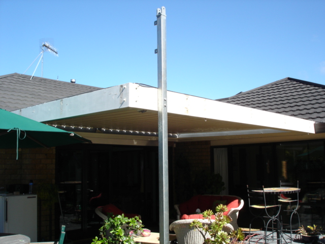
This design actually began when we bought another house and moved about 8 years ago. The house had a patio with a louvered roof supported by the house on three sides and with a wooden 4″ x 4″ square support pole for the far corner. Sadly the support pole was rotting out where it was seated in the concrete. It had to be replaced and I decided that it must be replaced with galvanized square steel section. That idea then morphed into the base of a tiltover mast for a Tri-Bander antenna. The photographs below will tell the story of how the mast was actually constructed. The upper and lower sections of the mast are 6 Metres long and the lower section is 4mm and the upper section was 3mm in thickness. The bottom 3.2 metre support pole is 90mm square section. All three sections were purchased fully galvanized from a local steel supplier. There is about a 2 metre overlap when the upper section is fully extended. There are few specific measurements because the mast was designed specifically for my patio roof support but the basic principles are there. Rough drawings of the rotator mounting platform and the lugs are also shown.
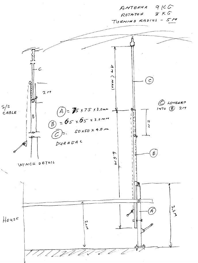
Rough sketch for the mast.
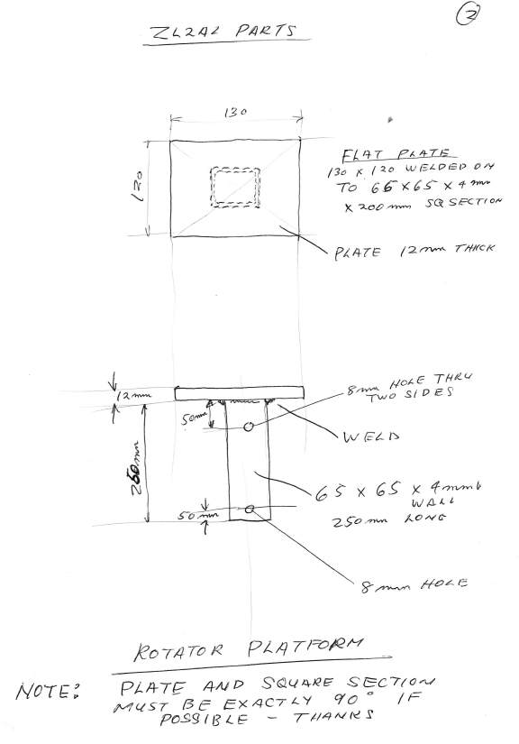
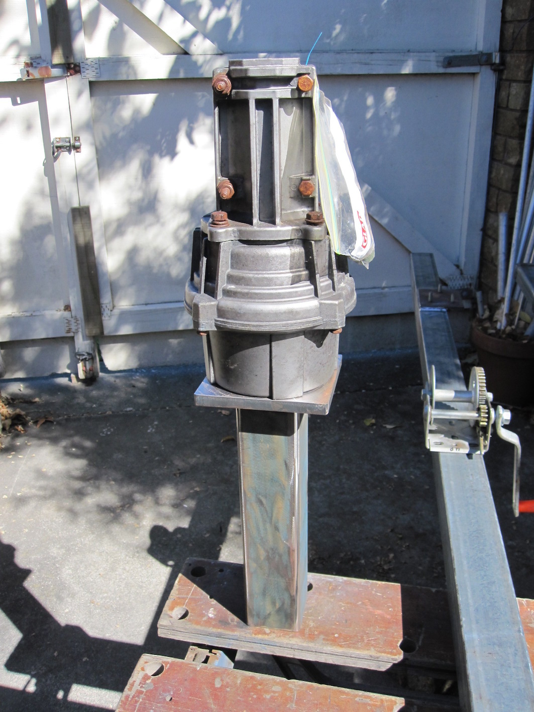
Rotator Platform Details

Details of lug fittings all made from scrap mild steel.
Once the lower section was completed, it was bolted to the pergola roof and mounted in place to replace the old wooden pole.
The lower section mounted in place ready for the upper section. Note the 2 logs at the top of the pole where the temporary gin pole is mounted to raise the lower section up ready to insert the hinge pin.
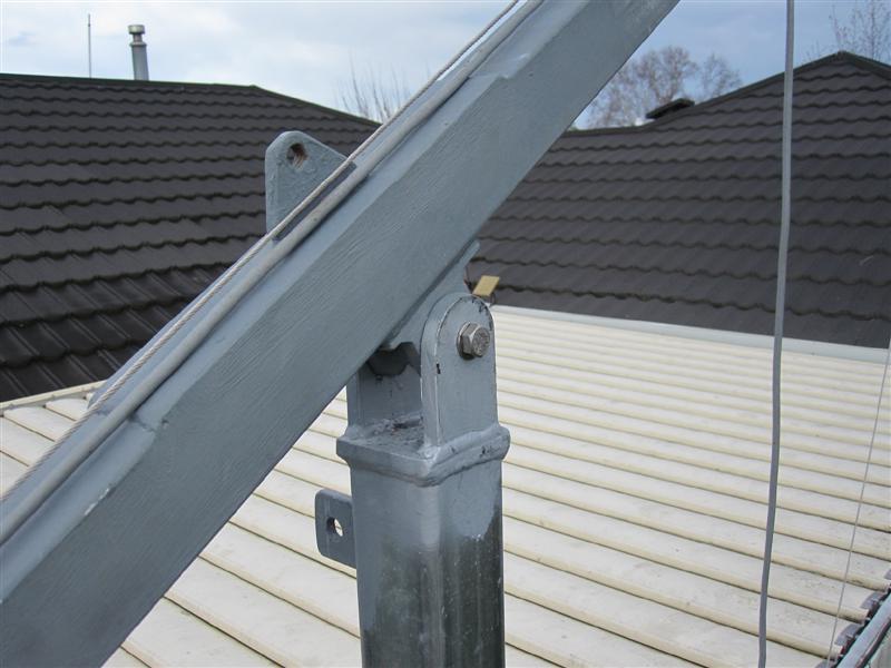
You can see the mount on the top of the pole. You can also see two lugs up near the top of the pole where I attached a Gin pole. This allows me to place the top section of the mast horizontally on the ground to attach a cable from the #2 lower winch temporarily bolted to the base of the lower section. It is simple to wind up the winch and raise the upper section up to the hinge where a 3/4″ stainless steel bolt can be pushed through and secured.
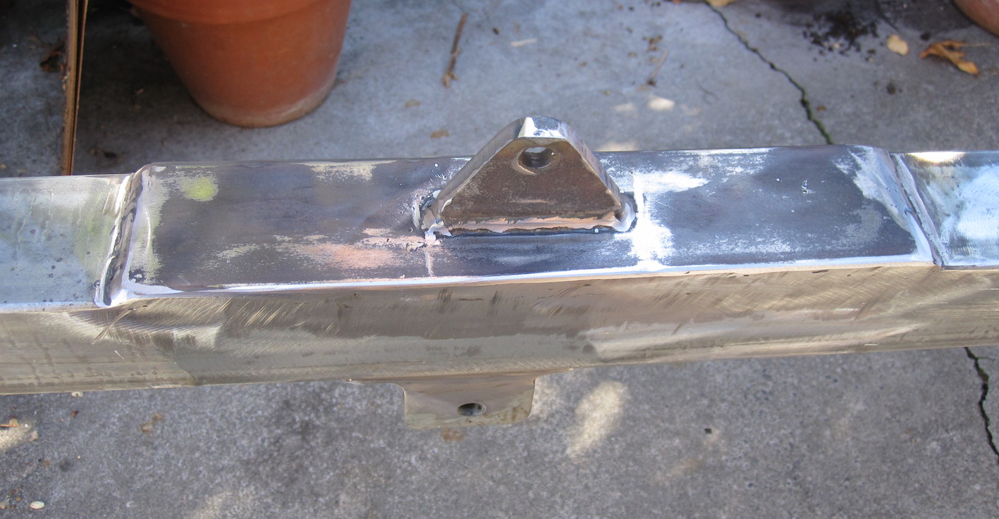
The centre of the upper mast section showing the lifting lug above and the hinge lugs below. of course, all exposed raw steel was painted with galvanizing paint before mounting in place
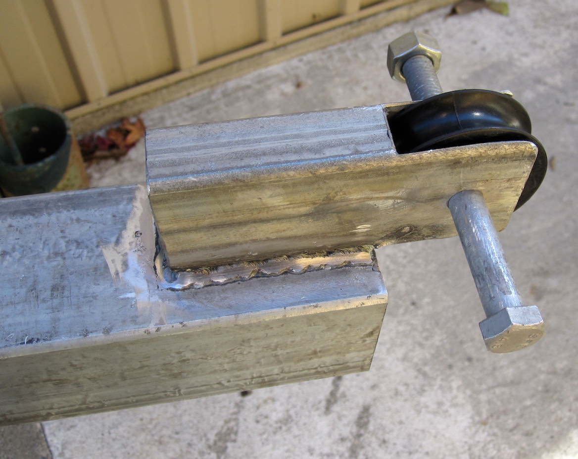
This is the lower mast pulley at the top of the lower mast. It is of Ocean Yachting grade and NOT cheap plastic as are all the pulleys. The long bolt is only temporary and a shorter one was used in final assembly.
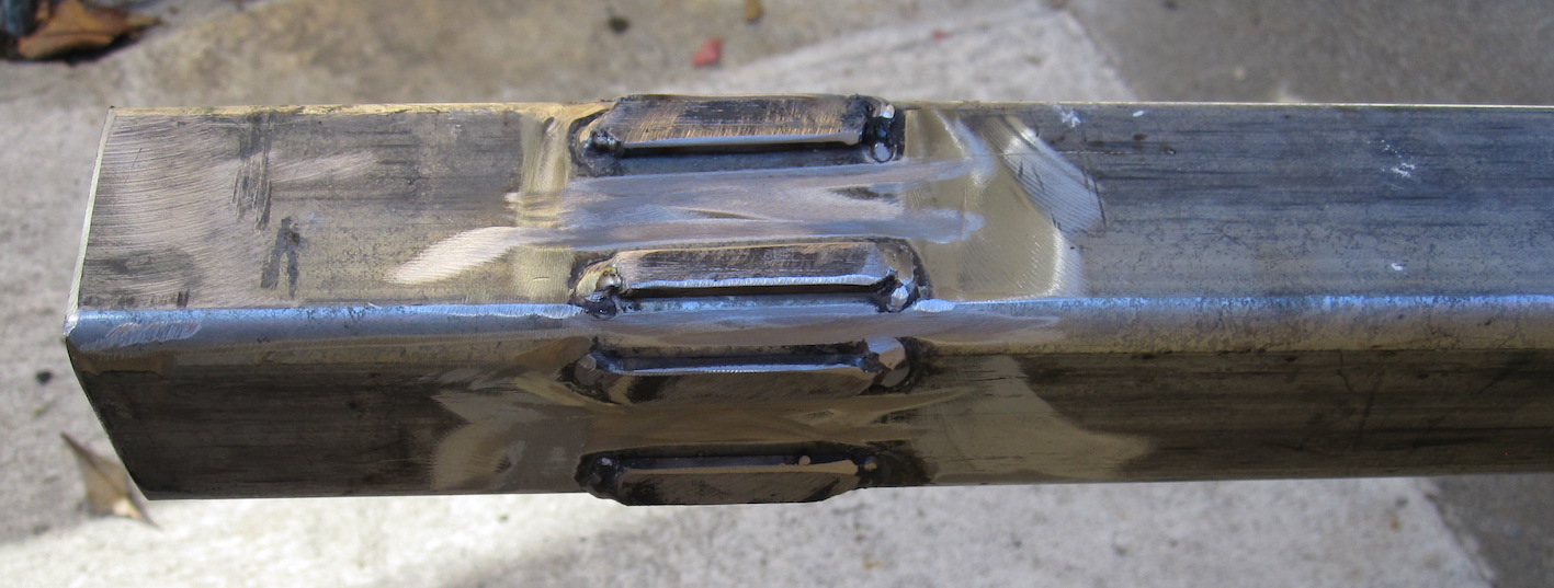
Due to the upper and lower square mast sections having a considerable “Gap”, we welded in 1/8″ “Shims” on the four sides of the upper mast to prevnt a lot of side play and rotation of the upper mast within the lower mast.
The upper section is then horizontal and tilted over ready to attach the rotator and mount the antenna. The Gin pole is then removed and the #2 winch cable is attached to the end of the upper section and the mast can be moved from horizontal to it’s vertical position. The winch cable and winch is then unbolted and removed after the upper mast is secured to the lower mast. It isn’t obvious from the photos but the extender cable is routed as follows: Cable goes from #1winch to top, over the pulley, down inside the mast in the spaces between the upper and lower sections to the bottom pulley, The over the smaller lower pulley and back up to top of bottom section where it emerges and is anchored with a bolt! The smaller #1 winch, when wound extends the upper mast to it’s full 30+ feet in height with about a 2m overlap.
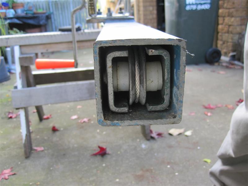
Looking at the bottom of the lower mast with the bottom of the upper mast fully inserted. Not the pulley which allows the #1 winch to crank up the upper section.
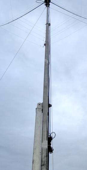
Although the mast is self supporting, I have attached 3 x 3/16″ nylon guy ropes to prevent swaying in heavy winds. The mast has withstood 120 Kph gusts quite easily over the past few years.
Mast Hinge with 3/4″ SS hinge bolt inserted. The upper section lifting log can be plainly seen protruding from the upper surface of the upper mast.
I decided to mount the rotator on it’s own platform and sleeve which fitted over the top of the upper mast section. It is simply secured with a couple of bolts which allows the rotator to be easily removed for service.
Rotator and sleeve assembly. The #1 winch for extending the mast is shown mounted on the lower mast section. The plate for the #2 temporary winch is shown further down the mast section.
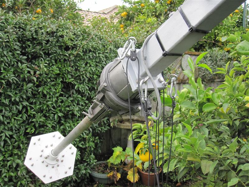
Sleeve, rotator and antenna mast in place ready for a Hex beam. Note the halyard pulleys and shackles ready for mounting and raising the other wire antennas and attaching the guy ropes.
The mast originally held a Hex Beam which works well for several years until it fell apart due to the harsh Hawkes Bay U.V. sunshine perishing the nylon cable ties which held the element wires in place. I decided at that point to built a copy of the Force 12 C3S which would be light, cover 5 bands with no traps and would give reliable service for many years. the story of the C3S construction is here Force 12 C3S in another section of this website. The C3S has been a great performer for me.
Original Hex Beam in place on the new mast.
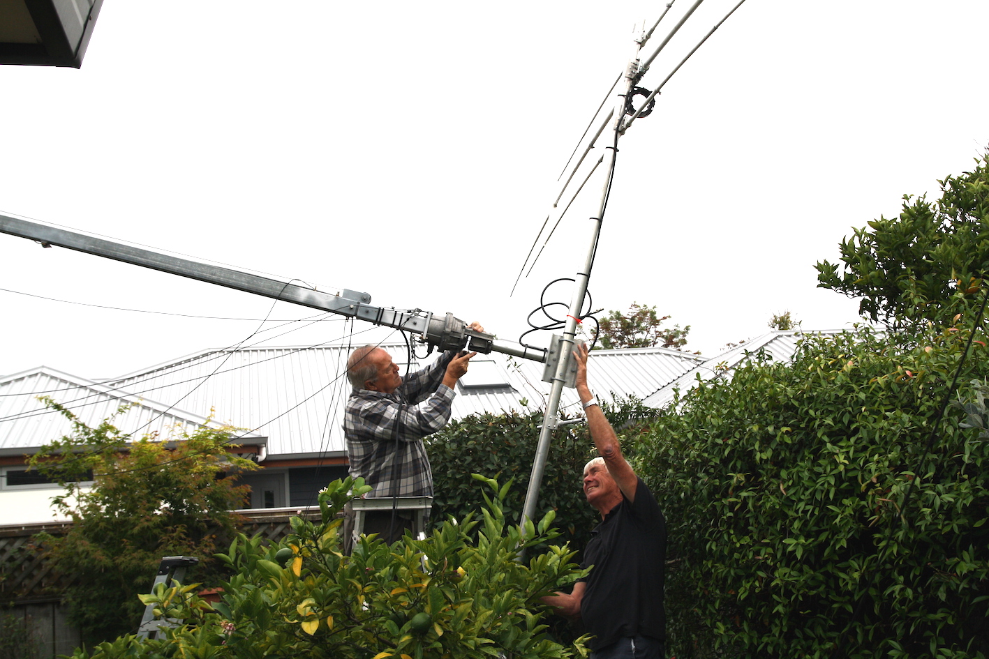
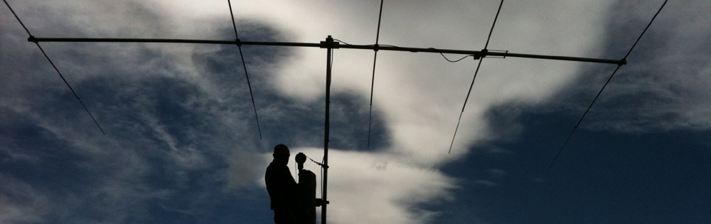
ZL2AO and ZL2TJ finishing the mounting of the Force 12 C3S ready to raise in place.
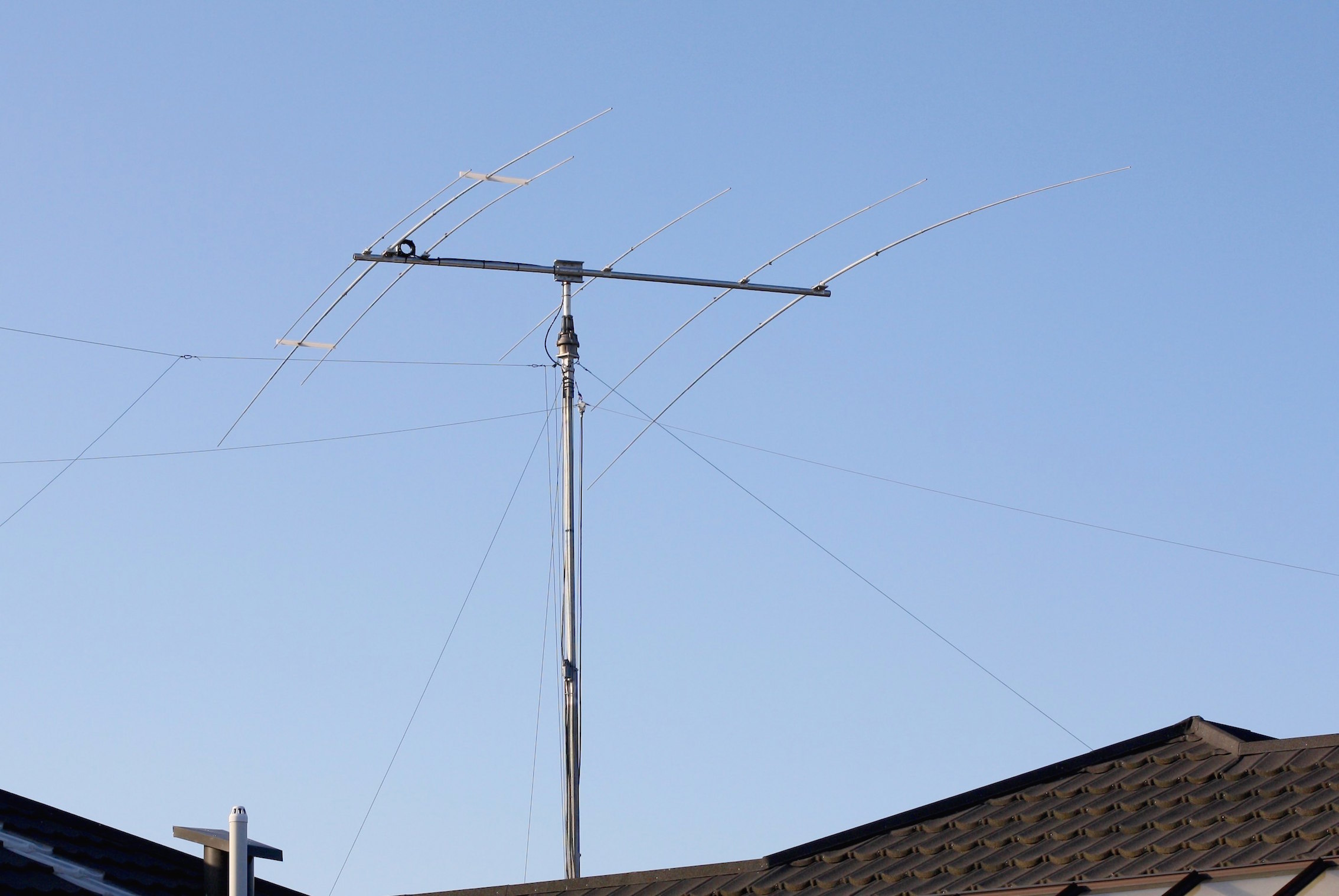
Mast raised in place with the new copy of the Force 12 C3S.
The mast has been an interesting project. I have some basic welding skills but my mate Morrie, ZL2AO is an engineer and knows what must be done to make sure a mast of this size stays intact while raising it and stays in place in high winds. He did all the welding for me.
The final antenna is shown in place in the photos below. Morrie and Carl helped me put the antenna in place on the top of the mast. 36′ elements are a lot to contend with the antenna on the ground in your back yard while trying to avoid trampling plants in your wife’s flower garden!!!! The whole project took a lot of time but not a lot of money. The total cost for the mast was around $650 USD and the C3S yagi was about half that price.
73 de Lee, ZL2AL