How to Use Your Antenna Tuner by Scott – N4ZOU
There’s more to it than what is in your manual or on most how to do it websites!
What more is required other than an SWR meter and properly setting the network components for matching the feed line to the antenna tuner?
This article is really about how not to burn up your antenna tuner and keep the losses to a minimum. It’s the little secrets that the manufacturer never wants you to know about and why that inductor, switch, or capacitor arced over or burned up. Here is a link to a site that provides some good information along the lines of this article.
http://www.tasrt.ca/AntennaTips/AntennaTips.htm
First of all a so-called antenna tuner in the modern since is really used as a feed line matching device. The only link between it and the antenna is that it shares the feed line with it. You’re not tuning the antenna at all. Your just using it with your modern transceiver so you do not burn up that expensive set of output transistors (or tubes) and the output power will not be reduced due to a match that is not very close to 50 ohms.
Now, lets talk about commercially built antenna tuners. Open up the manual and look for the information that tells you what conditions it won’t match. Are you there yet? Most likely you will never find that information! A modern “T” network with two capacitors and an inductor (or the AEA tuners with two inductors and a capacitor) will match a wide range of impedance ratios but they have their limits as all antenna tuners do. What is the limiting factor? The voltage and current rating of the capacitors, inductors and switches used. It’s as simple as that. You really can’t use the rating provided by the manufacturer on today’s modern antenna tuners. Say the antenna tuner is rated at 300 watts. OK, 300 watts at what impedance and reactance? Nope, that’s not in the manual! If you try and match very low impedance of say 15 ohms with that so called 300-watt antenna tuner with 100 watts the capacitors and switches will arc over from the several thousand volts developed across/through them. Even a so-called legal limit antenna tuner is going to develop problems in this situation.
So how do we deal with this problem? First of all we need to know what the impedance is at the end of the feed line. There are several ways to do this.
- Use an SWR analyser.
- Use a noise bridge.
- Use an external SWR meter.
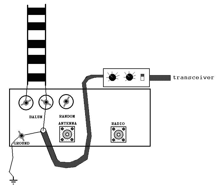
The analyser is expensive if you don’t have one already or can borrow one. Simply hook it to the end of the feed line where it would connect to the tuner, ladder line or coax. Coax requires no special attention or calculation, as it would connect directly to the output terminal of the antenna tuner. Ladder line feed will require some basic math if used with some type of Balun. Normally this would be the internal 4:1 Balun used in modern antenna tuners. Example: impedance reading is 200 ohms so dividing by 4 would provide a 50-ohm match. Another example: impedance reading is 25 ohms so the impedance on the other side of the internal Balun is going to be 6.25 ohms…this is going to be a problem! We will deal with this situation later in this article so lets continue.
How do we know if the Balun really is 4:1? It might have been designed as a 4:1 Balun but the type of ferrite used could change the actual transformation along with other factors involved. It’s better not to assume that the Balun is 4:1 and do the math just to find out it was not doing what you would think a 4:1 Balun should be doing! Simply connect the meter to the Balun. Setup the ladder line and tuner in the position where it is going to be used. Disconnect the bar or wire connecting the random wire post from the Balun connections and clip the meter to the Balun post where the bar or wire would connect to the random wire post and the other meter lead to the tuner ground post. Now you can read the impedance/reactance or SWR through the Balun. 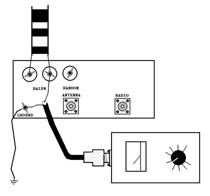
Check this site for information on Balun design. http://www.qsl.net/iz7ath/web/02_brew/11_balun/pag01_eng.htm
The noise bridge requires you hook it up so you may hear the noise generated when using it. Simply hook the noise bridge to the Balun and transceiver, select the desired frequency, adjust the noise bridge and read the impedance and reactance.
If all you can manage to use is a SWR meter hook it up to the Balun and your transceiver this way. 
This will require you to transmit so select a frequency that is not being used and only use a power level that will allow you to get a good reading with it. You can’t tell if the impedance is high or low using an SWR meter but if the SWR is 3:1 or lower you can safely use your tuner if the impedance was on the low side of 50 ohms. If the impedance is off the scale or reads very high or very low on the Analyser,NoiseBridge, or SWR meter you will need to change it so your antenna tuner can match it.
How do we change the impedance at the end of the feed line on coax or ladder line? By making the coax length longer or shorter! Wire Multi-band antennas used on the HF bands almost never have an impedance matching device between the antenna element and the feed line. Even antennas that do have them will not produce an exact match for the feed line across the entire band. This sets up a condition on the feed line where the impedance will be different across the length of the feed line. Generally, the impedance will repeat the element to feed line impedance every 1/2-wavelength times the feed line velocity factor. Changing the feed line length will change the impedance reading at the transceiver end of the feed line. A simple feed line matcher to allow inserting different lengths of feed line between the antenna tuner and the point where the feed line terminates in the shack at the mounting point on the strain relief or feed through. This setup works for ladder line and coax feed lines. Lengths used are 1, 2, 4, 8, and 16 feet long for coax or ladder line. If you operate on 160 meters you will need another length of 32 feet. One or more of these lengths will, in most instances, provide impedance your antenna tuner can live with. Generally speaking this will be between 50 and 600 ohms for a good antenna tuner. Anything above or below will cause substantial loss through the antenna tuner and problems will develop.
The safe thing to do is find a feed line length where the SWR is 3:1 or better. Not only will the loss be less across the capacitors, switches, and inductors you will be able to use the internal automatic antenna tuner in your transceiver. Just remember that the feed line used will be carrying high voltages and current according to the match between the antenna element feed point and the feed line. Select the proper feed line for your line matcher and installation! When you start using your line matcher you will need to make a chart on how much feed line to use. While your meter is connected to the back of your tuner simply check different frequency’s that you use on different bands and create a list of the require lengths to insert. You can make your line matcher as simple or fancy as you like. From just providing as easy way to connect different lengths between two connectors to a relay system with computer control! You could also find a length of feed line that will provide reasonable impedance on all bands. This is generally easy to do with resonant loop and dipole type antennas operated at odd multiple harmonics. I run a 160-meter loop sky wire and only insert a single 4-foot length of 450-ohm ladder line for the 12 and 17-meter bands. Here is an excellent site on building a line matcher and using it.
http://www.qsl.net/w5dxp/notuner.htm
Lets talk about that 25 to 6.25 ohm impedance transformation which would be found on an antenna like a short dipole or vertical antenna. 25 ohms would not be much of a problem but you don’t want to bypass the internal 4:1 Balun by connecting the ladder line to the random wire post and antenna tuner ground. The RF flowing on the antenna tuner case can bite you and it upsets the balance of the ladder line feed system. What you need is an external 1:1 Balun. This is simple and cheap! Simply wind about 25 feet of coax around a plastic form about 6 or more inches in diameter to make an “Ugly Balun”. Hook one end to your antenna tuner and the other end to the ladder line. Be sure to select the properly rated coax! You don’t want it melting or arcing at the ends. Be safe and use RG-8 coax for it. 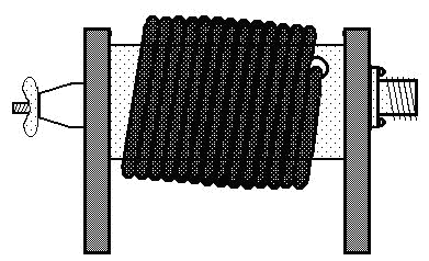
Did you buy a new or used antenna tuner and you find it works poorly or strange when used on ladder line? Do you want to check it and your balanced system just to make sure it really is balanced? This is easy and the equipment used is cheap and anyone can homebrew it!
Parts required:
- 2 #47 bulbs rated 6.3 volts at 150 mA.
- 2 bulb holders for use with the above bulbs.
- 2 to 3 feet of ladder line.
- 4 to 6 feet of hookup wire.
- 4 alligator clips.
Cut your hookup wire into 4 even lengths. Connect 2 of the lengths of hookup wire to the bulb holders. Connect each end of the hookup wire with the bulb holder in the middle to each of the same side ends of the ladder line using 2 of the alligator clips. Make the exact same setup for the other side of the ladder line. It’s very important to make them exactly the same. The 2 to 3 feet of ladder line forms a shunt for the bulbs on each side and both provide a balanced indicating system. The picture below should answer any questions on making up this simple and cheap test device. 
Insert this line into your feed system and using low power tune to minimum SWR on the line at the antenna tuner. Slowly increase power so the bulbs will illuminate but not so much that they burn out! If both bulbs show equal brilliance then your feed line system and antenna is operating properly. If one bulb is dimmer than the other or does not illuminate at all then you have something wrong. As a double check reverse the leads on your balanced feed line indicator and make sure the other bulb is not simply burned out. It should illuminate with the same brilliance as the other bulb. If it checks ok then you have a problem with your Balun, feed line, or antenna. If the feed line and antenna elements check out ok, with no breaks, cold solder joints, or poor connections then you have a bad Balun which will need to be replaced. It could simply be a broken wire, shorted turns, or the ferrite has been overheated and/or cracked.
There is an antenna that is used in a balanced feed system that is not inherently balanced that would show imbalance with your feed line and Balun working just fine. This antenna is known as an End feed ZEPP. They will tell you that the antenna is ready to go “as is” but it’s really not! To get the most efficient operation requires the use of the balanced feed line indicator when installing it. Install the ZEPP and the bulbs and clips from your balanced feed line indicator after striping just enough insulation to allow clipping the bulbs and alligator clips in the ladder line 2 to 3 feet from the antenna tuner Balun connections. Cut or lengthen the element as required to obtain a balanced condition on the feed line or change the ladder line length. Doing this will greatly improve the ZEPP antenna. Just remove the bulbs and alligator clips when you’re done. 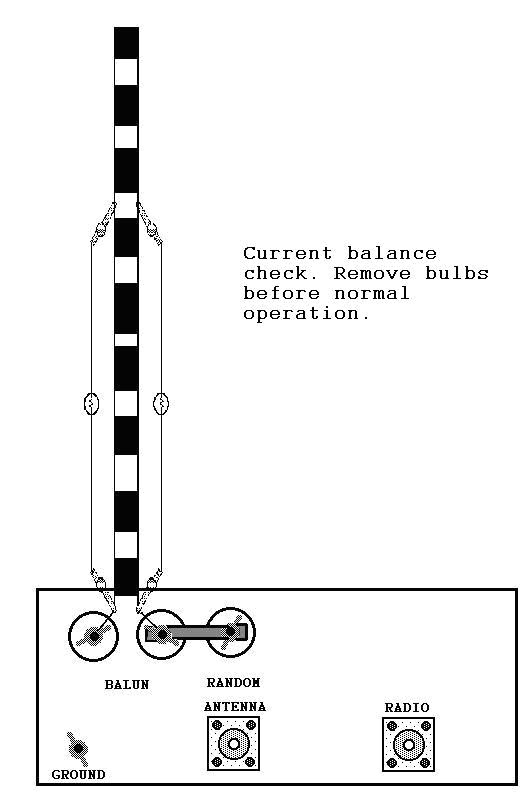
When checking a balanced antenna tuner like a Johnson Matchbox carefully look for bad switches, inductors, capacitors and other parts. Look at all the soldered joints and if they look bad, clean and re-solder as required. Here is an old 1Kw Johnson balanced antenna tuner that had no balance at all. 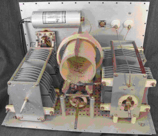
It looks like new but after removing several nuts holding down terminals with star washers it was found to have some ugly green tarnish in all the joints. After replacing all the nuts, terminals, and star washers and cleaning the studs proper operation was restored with very little or no imbalance anywhere on the 80 through 10 meters bands with a ladder line feed dipole. When you buy a used or homebrew antenna tuner never expect it to be 100% operational, even some new off the shelf units! Take it apart, inspect, and clean or replace all mechanical joints where screws and washers are used and make sure that all RF carrying Hardware is brass or copper, silver plating is a plus! If a magnet can pick up the hardware throw it away! You should do this with any new, used or homebrew antenna tuner you buy or build. As an example I once purchased an almost new antenna tuner from an upset buyer that had problems. After looking it over I found both capacitors had poorly aligned vanes that actually shorted out at near maximum capacitance! After fixing that problem and replacing all the steel hardware used with RF carrying parts with brass it turned out to be a nice little antenna tuner.
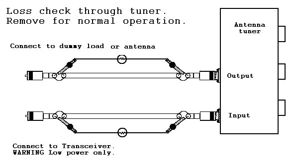
Speaking of checking out antenna tuners one thing to do is to check the loss through it. If you made the simple balance indicator you can use the two bulbs for an indication of loss through it, which will also show you if you have used the incorrect settings to provide a 1:1 SWR match. Cut two lengths of coax equal to the length of each of the bulb, holder, hookup wire, and alligator clips. RG-58 will work fine. Put the required coax connectors of your choice on each of the ends making sure to keep them identical. An inch or two behind each connector split the coax so you can connect a jumper to the center wire in the coax. It’s very important to keep both coax lines identical. 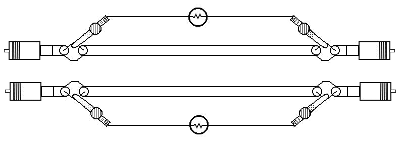
Now connect one of the coax test lines with the bulb clipped to the slits in each end to the input connector and the other test line of coax with bulb to the output of the tuner and feed line to the antenna. Now the center wire in the coax is used as the shunt for the bulbs. Simply tune up as normal at low power so you don’t burn out the bulbs and then increase the power so that the input bulb glows and note the bulb on the output of the tuner. It should glow at or just very slightly dimmer than the bulb on the input coax section. If there is a big difference then you have used incorrect settings for the tuner to provide a low SWR or you have problems in your antenna tuner. Again, double check and swap the coax sections to make sure you made them properly. If you get the same results then switch to a 50-ohm dummy load and reset the antenna tuner for a 1:1 match and recheck. At 50-ohms in and out of the tuner there should be almost no loss.
Double-check your antenna tuner settings. If it’s a new antenna tuner send it back! If it’s used then you need to go through it and thoroughly check it for bad connections or burned up capacitors, switches, inductors, or connectors. You can calculate the loss through the tuner. Use the dummy load and apply just enough power to just get a small glow from the input bulb and then back the power down just enough that it goes out. Write down the power required to do this. Now apply just enough power that the output bulb just starts to glow and write the power level required. Now swap the input and output cables and recheck and average the numbers. Now using simple math you can calculate the loss across your antenna tuner. When using a dummy load and your loss ratio is low or none then you have a good antenna tuner. If you get a large ratio of loss through the tuner connected to your antenna and feed line system then you should check things out and fix the matching problems before you run the power up and consequently burn up your antenna tuner.
You can use this setup with your internal Balun. Just connect a short jumper from the end of the coax that would normally go to a coax feed antenna and connect it the same way as shown above with the SWR meter between the output of the antenna tuner and the input of the internal with the jumper from the random post disconnected. Now you can do a check and see if you have the proper inductor and capacitor settings with your balanced antenna system. Just remove both coax sections and hook the Balun back up normally and use the selector switch to select the random post for use with the Balun.
As you can see, it’s not all that difficult to properly setup and use your antenna system if you have the required knowledge and simple tools to do it with. The problem comes with some manufacturer that does not want you to know how to check out your antenna tuner. I can’t even guess at the number of them that have been built and sold using poor construction materials and practice in assembling them. If you burn it up they may claim it’s your fault and in some cases they are correct but they did not supply you with all the required information and tools you needed, which would have also allowed you to see any and all problems with the quality of there product. Sort of a catch 22 situation from the old movie of that title!
Just a quick note to all about my recovery. My neurosurgeon gave me my driver’s license back and sent my therapist (thera-pest) packing! I can now use power tools and I can get around pretty well but I still have bouts of confusion, weakness on my right side, and this strange problem with numbers. He can’t tell me if this will ever go away. I am still alive and kicking anyway! Oh the pleasures of a drill press and jigsaw on a homebrew project!
73 all and happy operating. Scott N4ZOU

