When you are a new ham it doesn’t take very long until you realize that DXing on the higher bands is a tough ask if you only have minimal wire antennas. Over the years I have had many commercial antennas including the classic HyGain 204BA and the HyGain TH6DXX. These are very big antennas which require very big towers to hold them up. A few years ago it was time to move to a smaller residence and the TH6DXX had to go. Our new property has a smaller footprint which limited the size of the antennas. I struggled to break the pileups with a small mast and trap dipole and decided to build a 35 foot telescoping mast with a small yagi on top. I decided to build a copy of a very successful commercial antenna which utilized 2 elements each on the 10M, 15M and 20M bands. It also worked on 12M and 17M with unity gain. This particular antenna design has no traps and the 6 elements were interlaced on the 14 foot boom. The 20M driven element is fed and the 10M and 15M elements are closely sleeve coupled to the 20M element which meant that only one feedline is used. The design appealed to me. The write-ups on eHam looked good so I started accumulating used aluminium tubing for the project.
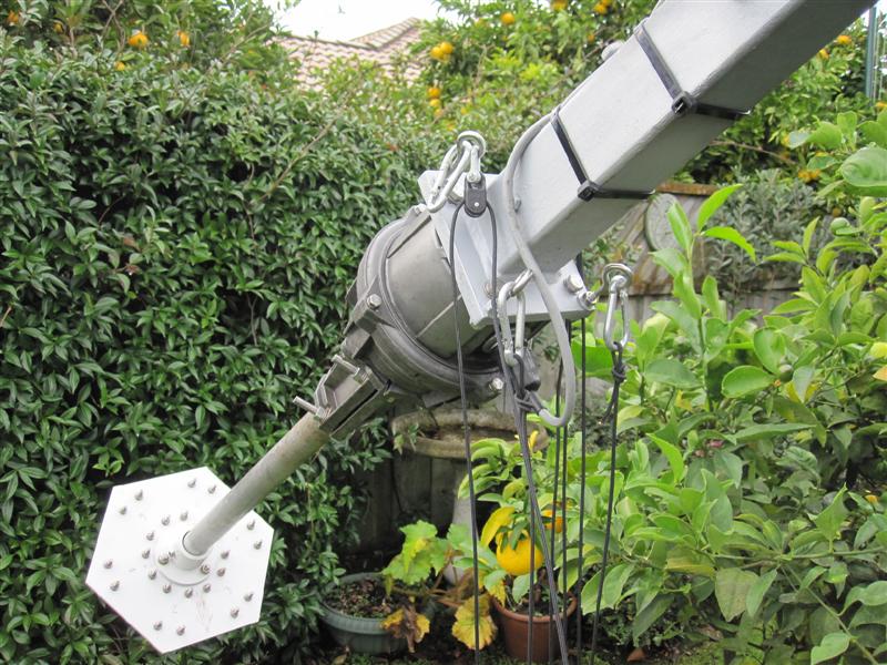
Unexpectedly, a local ham generously offered me a Hex Beam which was smaller, lighter and basically was a two element yagi on each of he HF bands. It had nearly the same specs as the yagi I was about to build. I accepted the offer and with the help of some local hams it was up on top of the new mast. The HexBeam worked very well indeed. My DXCC totals on 12M went from 42 entities to 187 in 18 months. I could work most of the DX that I could hear. Although I wasn’t the first to break the pileups the Hexbeam worked quite well. My amplifier helped of course. Over the 18 months it was up we had several robust wind storms. Nothing of hurricane force hit it but one day I noticed a wire hanging down. I also noticed that 10M didn’t work very well and was tricky to use even with the tuner. Over the past 6 months, more wires separated from the spreaders and are hanging down.
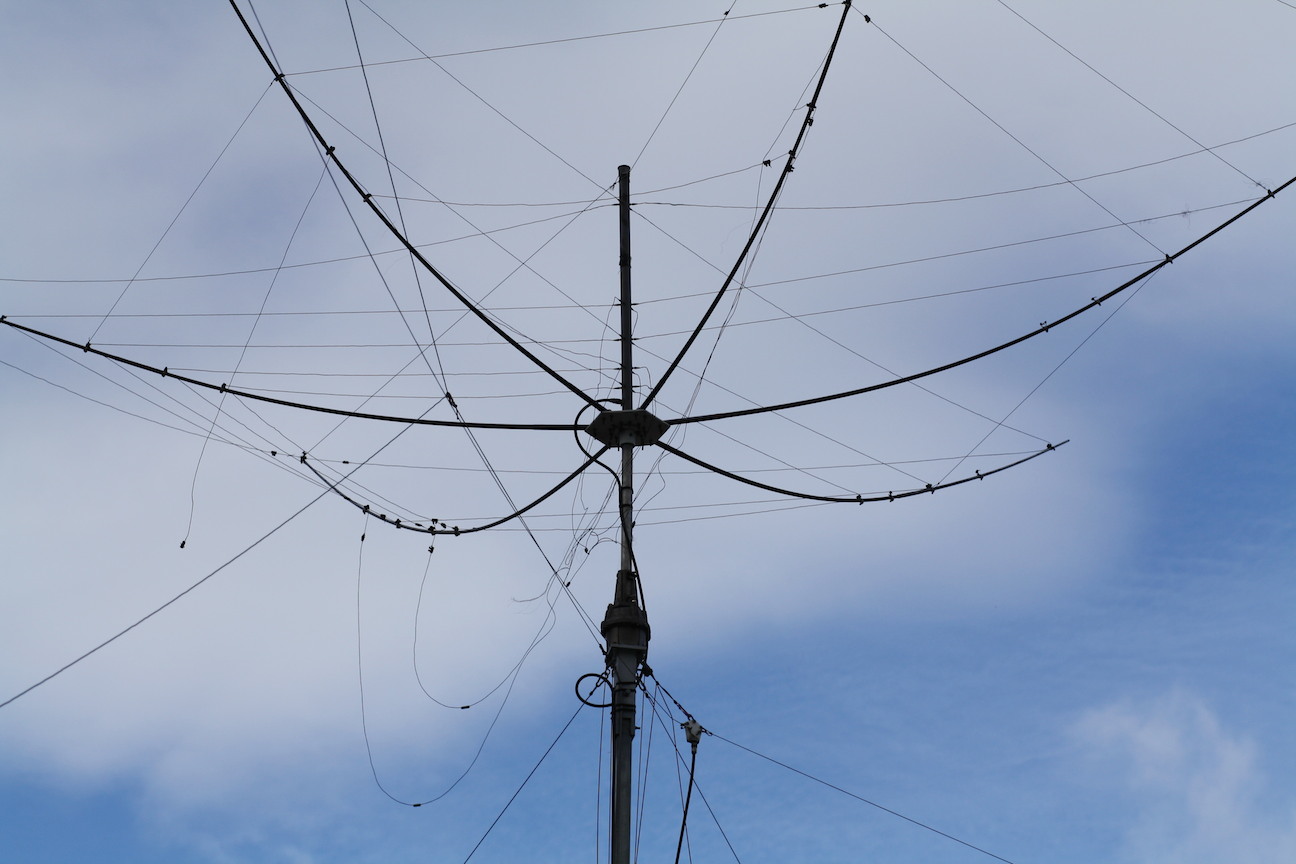
Existing HexBeam with wire elements in disarray
Strangely, the antenna still works on 20M and 15m but the performance is off to say the least. The other problem is that when I feed power into the antenna, the SWR fluctuates and the amplifier protests. I made the decision to carry on building the new yagi. It seems to me that solid aluminium tubing will probably stay up longer with fewer problems. I dislike disconnecting wire dipoles and loops from masts and lowering antennas to change them.
Element construction
I cannot believe how much aluminium tubing is stored under ham’s houses, in their back yards or in garages. Used aluminium tubing works just as well as brand new tubing. It simply has to be cleaned up. As I started this project I sourced much of the tubing that way. In metric countries like New Zealand, new tubing is supplied in metric sizes. Many old antenna designs and old tubing lying around is in Imperial size. The two sizes are generally not compatible for sections to slide into each other. The equivalent size of 1 inch in metric is 25.4 millimetres. And if you wish it to slide into the next size up it will be .4 mm too large and won’t fit. Generally a tapered element consisting of sliding tubing must be all metric or all Imperial size. You may have a metric sized Director and an Imperial sized Reflector.
This particular antenna design uses 25mm (1”) tapering down to 10mm (3/8”) sections in 1.2 metre (4 foot) lengths. That is very convenient as the new lengths come in 4.8 metre (16 foot) lengths from the factory if you choose to buy new and you get 4 sections from each full length. The surface of old aluminium tubing is a bit of a challenge to clean up. A little fine emery cloth (240 grit) or steel wool will do the job quite nicely. Cleaning the inside of the tubes was a big problem until a friend suggest rifle cleaners. The rifle cleaner is 10mm diameter and has about 3 inches of brass bristles along it’s shaft. The shotgun barrel cleaner is about 1 inch diameter for larger tubing. I soldered a 6 inch brass shaft on to the cleaners and used a cordless drill to ream and clean the inside of the old corroded tubing. The result is magic and finished in a few minutes! You can see the result in the photo below.
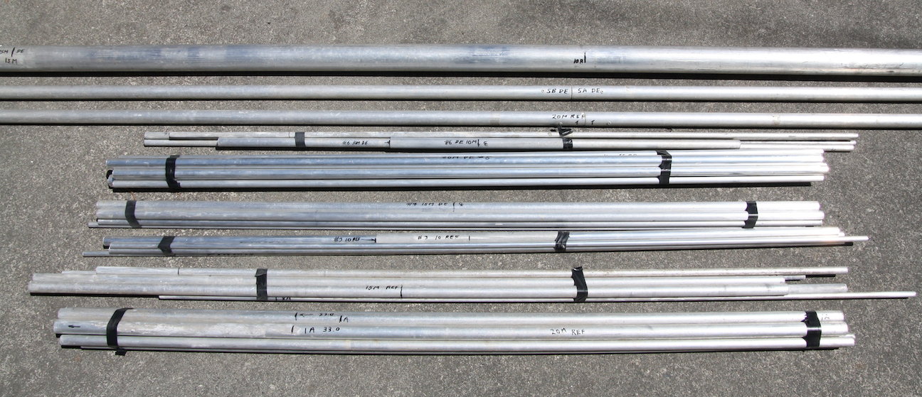
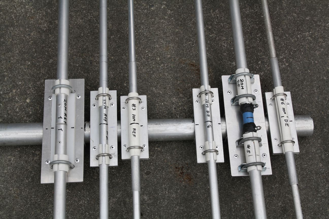
The element packs and boom made from new and used alloy tubing.
The elements are cut to size, measured, double and triple checked for correct measurement and each element is bundled and taped ready for final assembly. Each element section is “pop riveted” into the next section with two 1/8″ pop rivets. I also used conductive grease for each joint. Each element is in 3 sections. The centre section is clamped to the boom and each of the 2 outside pop riveted sections are inserted into each end of the centre section. The outer two multi tubed sections are hose clamped to the centre section to allow for final adjustment. It also allows easy assembly on the day of placing it on the mast or tower.
Element to Boom Clamps
I managed to find a old “U” shaped piece of aluminium that looked like it would be perfect for the right angle clamp side pieces.
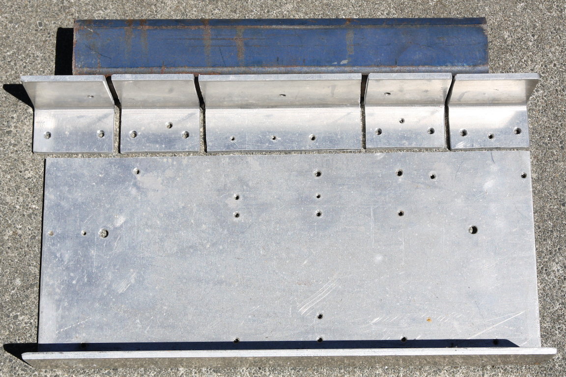
angle pieces cut from scrap aluminium
The material was 3/16” thick and high tensile alloy but was large enough to make five sets of clamps. All I had to do was buy a section of 3/16” x 3” x 10” flat plate and cut sections for the element support plates. All cutting was done with a hand jigsaw fitted with a good quality metal cutting blade.
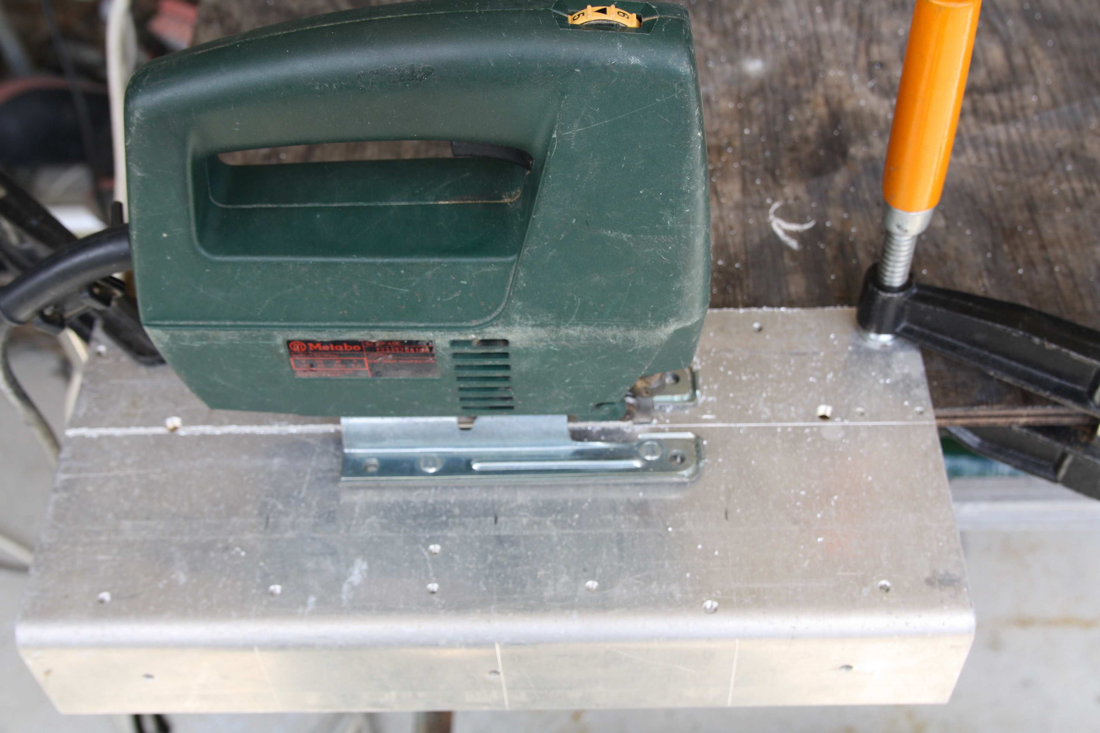
Cutting the plate
The cut leaves the alloy a bit rough but it is easily cleaned up with a small hand grinder with sanding pad or a file may be used. The boom was exactly 2.0” diameter so I set up a length of scrap 2” square steel section, clamped the side angle pieces in place and then clamped them to the top plate. The square section may be seen in the photo along side angles that were just cut. The “G” clamps held the angle pieces and the top plate together while the four 3/16” holes were drilled. The 3/16” pop rivets held the whole clamp together ready to be pop riveted to the boom.
Finished Boom to element Clamp
This antenna design called for 2 full size elements for each band. The 20M driver element was split in the centre and made a bit differently with a longer support plate. Each element was electrically insulated from the boom with sections of plastic electrical conduit slipped over the element middle. The photo below shows all six finished element clamp assemblies sitting on the boom.
Six elements sitting temporarily on the boom before being moved into place and riveted
Making the Driven Element
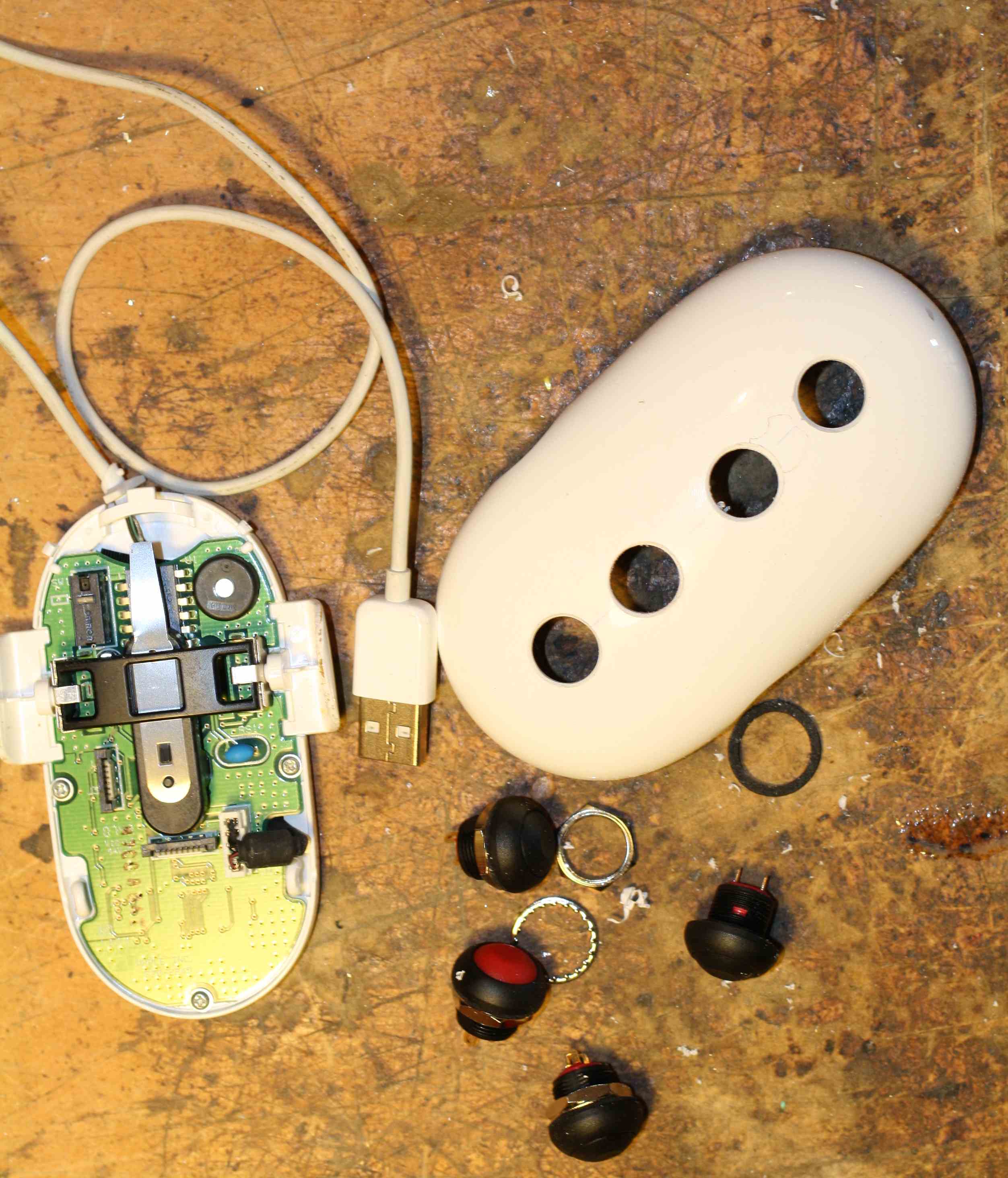
Feeding a Yagi with power while obtaining a good match for the radio has always been a problem. Over the years Gamma matches, Hairpin loops, Delta matches and other methods have given way to 50 ohm coaxial cable feeding the split driven element through a balun. The split element needs some type of insulating rod at the feed point into the ends of the two tubes. I could have bought a small length of fiberglass tubing, but a local store was selling fibreglass handled hammers cheaply and they would do very nicely.
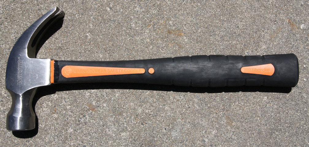
Cheap Hammer!
The handle was covered in rubber but with a little work with a small grinder, the fibreglass centre support took shape and fitted into the tube ends.
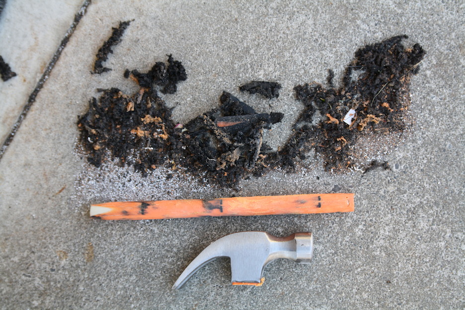
The Fibreglass Centre Rod emerges
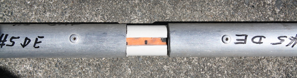
Rod inside tubing ends and split PVC spacer in place
A couple of bolts to attach the balun and some weatherproof sealing tape finished it off and it was mounted on it’s clamp plate ready for connection to the balun.
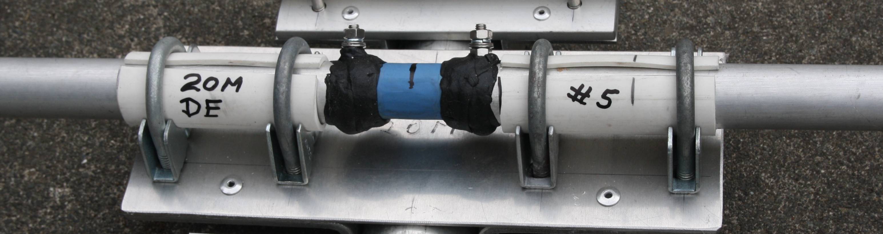
The finished split driven element ready to go into DX battle!
The photographs tell the story. In retrospect, a correctly sized fibreglass tube would have been easier.
Balun Construction
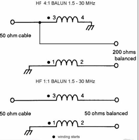
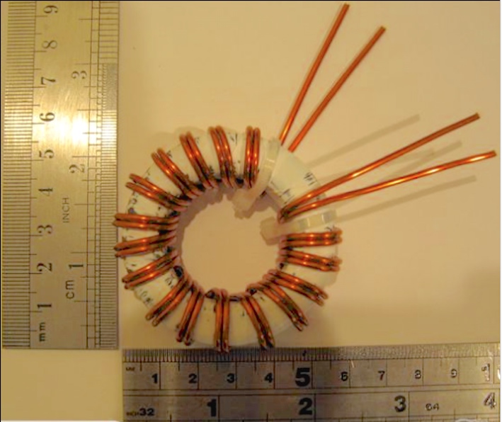
Baluns come in all forms and sizes but sometimes the simple coil of coax cable works very well indeed. Many articles have been written on the diameter and the number of turns but I settled on 6 turns about 5 “ diameter and wound them inside an old plastic tube. The data is from an article written by Ed Gilbert WA2SRQ
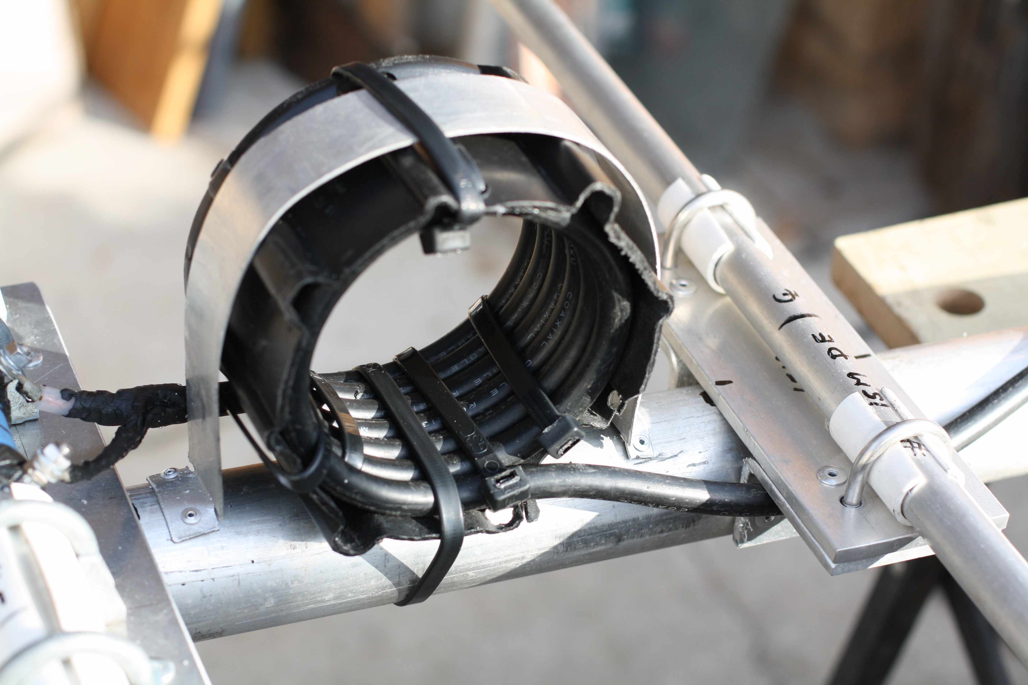
The Completed Coaxial Balun Place
I have used this type of Coaxial Balun previously and it works very well. Most articles on balun construction suggests that winding the turns over a short piece of PVC is the way to go. Winding the turns inside the tubing is much easier and the naturally slide into place. And then the turns are secured in place with plastic cable ties. I made up a clamp from thin scrap aluminium which is held in place with 1/8″ pop rivets. The balun is virtually immovable. Connections to the driven element are sealed with amalgamating sealing tape to prevent moisture creeping back down the coaxial cable. This system worked well for me on another similarly constructed 20 metre yagi I built a few years ago and I have used it on other similar antennas.
Mounting the Elements to the boom
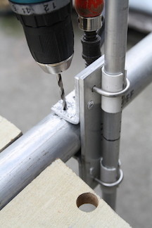
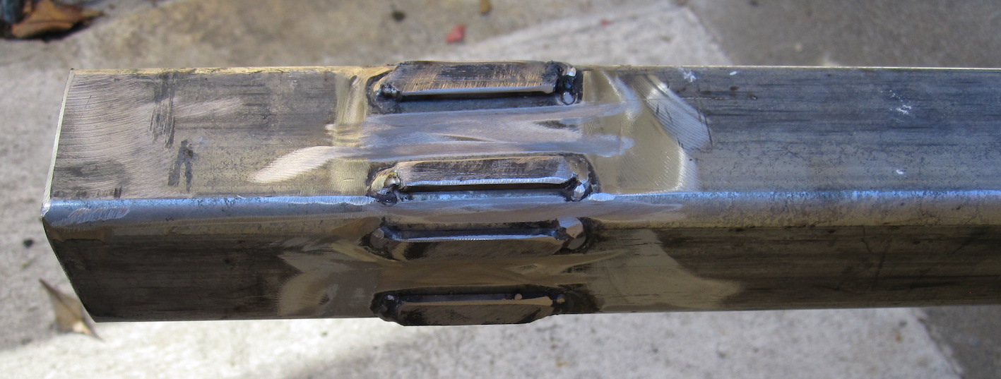
Drilling the rivet hole in the boom. Note the F Clamp at the back holding the assembly in place
The next stage of mounting the elements is not all that difficult. I clamped the boom in the jaws of a work table ad then marked where the elements would be mounted. I check the measurements again and then again a 3rd time. I placed one of the 20M elements on the boom and clamped it so the bracket wouldn’t rotate as you can see in the photo. It was a simple matter to drill out the 1st 3/16″ rivet hole and fix the rivet.
The 2nd hole was on the other side angle and it was riveted. Now in place, the clamp couldn’t move and the remained holes were drill out with the cordless drill and the clamp was secure.
The photograph below shows the three close spaced driver elements mounted on the boom and their angle plates riveted.
10M, 20M and 15M Clamp Assemblies with insulated elements
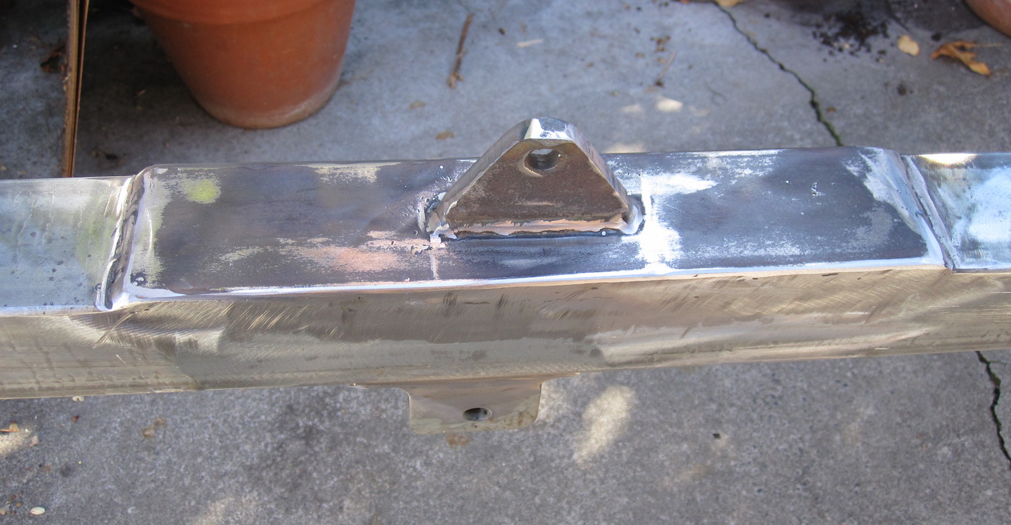
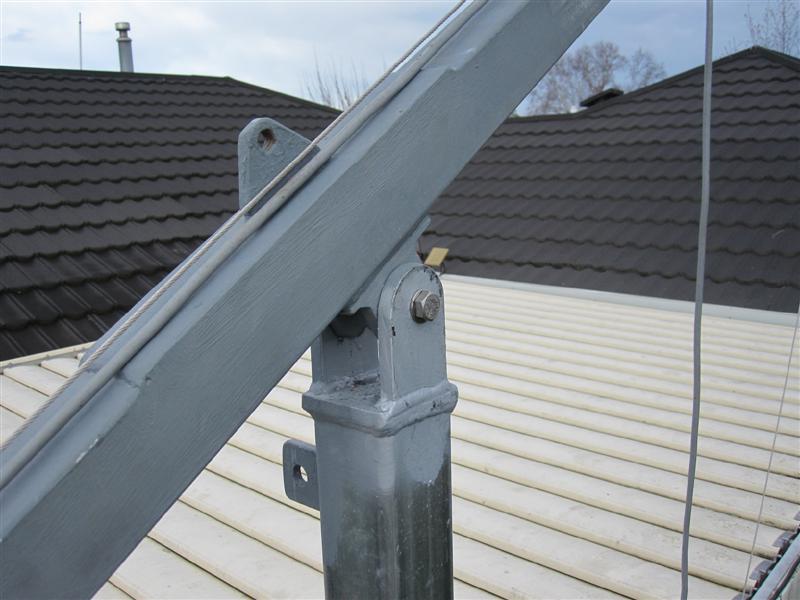
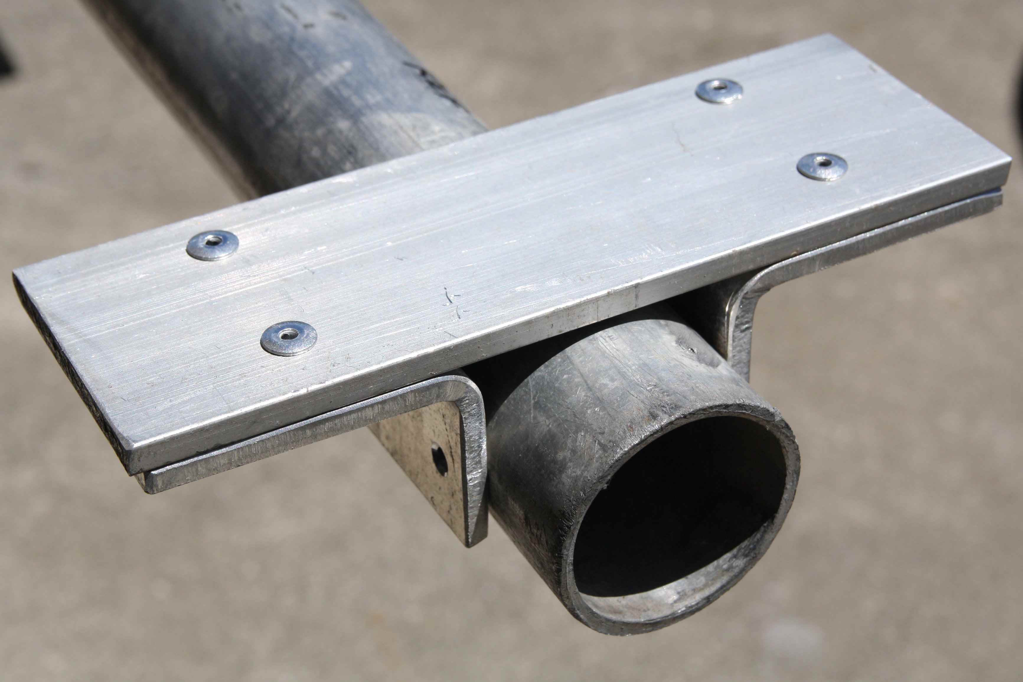
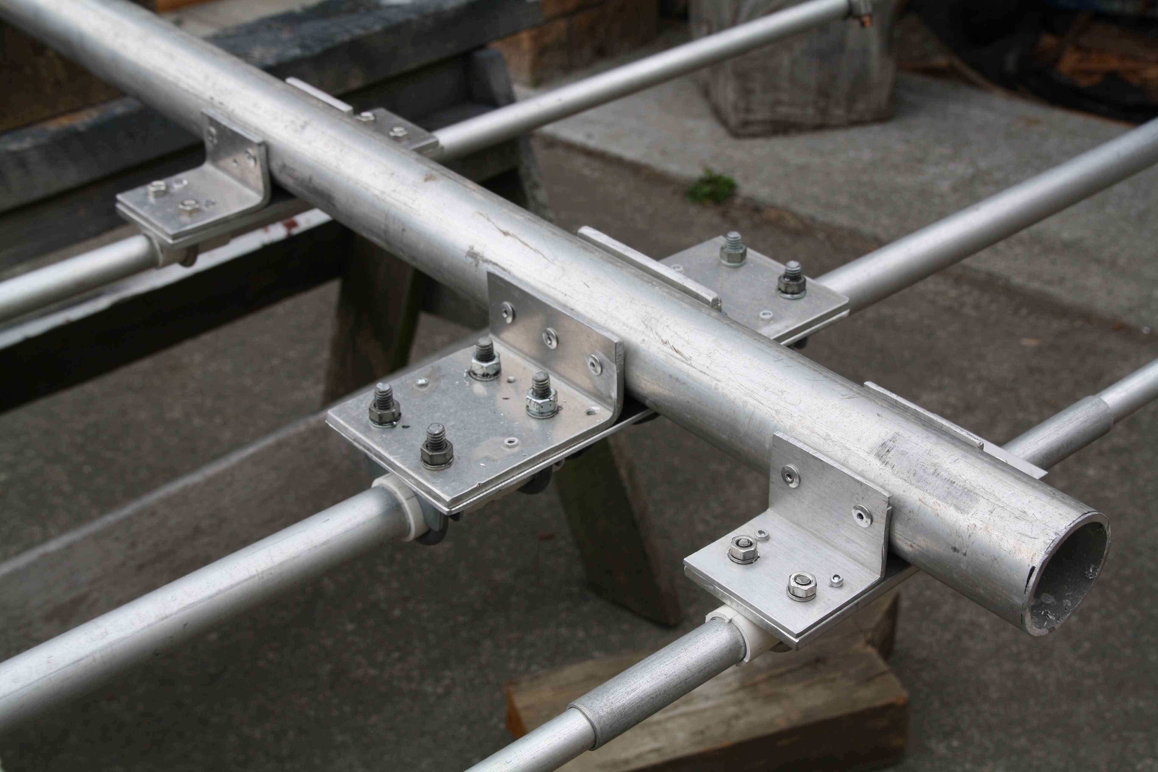
The mast to boom plate was made from an old used piece of alloy “U” section. The section it wide enough on both sides to fix a pair of 2″ “U” bolts in place to hold the mast and boom together. One of the problems with “U” bolts and muffler clamps is that the mast or the boom will, over a period time start to rotate within the clamps. If you tighten the clamps you end up on a never ending spiral of constantly tightening the nuts on the U bolts which will distort the mast or the boom. This can easily be prevented with a single 3″ bolt through mast and plate. Another is placed through the boom and plate. This absolutely prevents rotational movement and the U bolts do not need to be tightened beyond limits. You can see the whole assembly below.
Mast to Boom section plate with long bolts to prevent rotation. The small holes on the boom are there as the boom was previously used in another application. NOTE: The “Mast” marking on the horizontal tube actually marks the centre of the mast placement. The vertical tube is the mast and horizontal is the boom section.
Time to Finish the Project
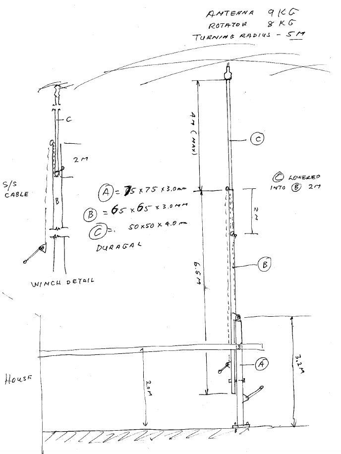
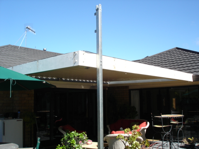
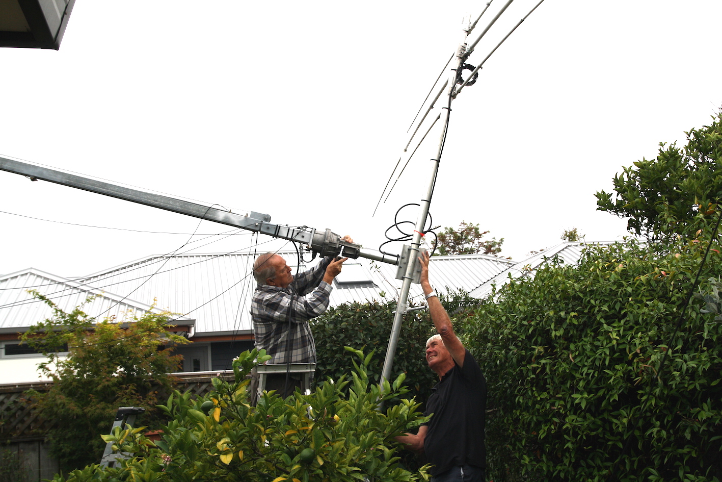
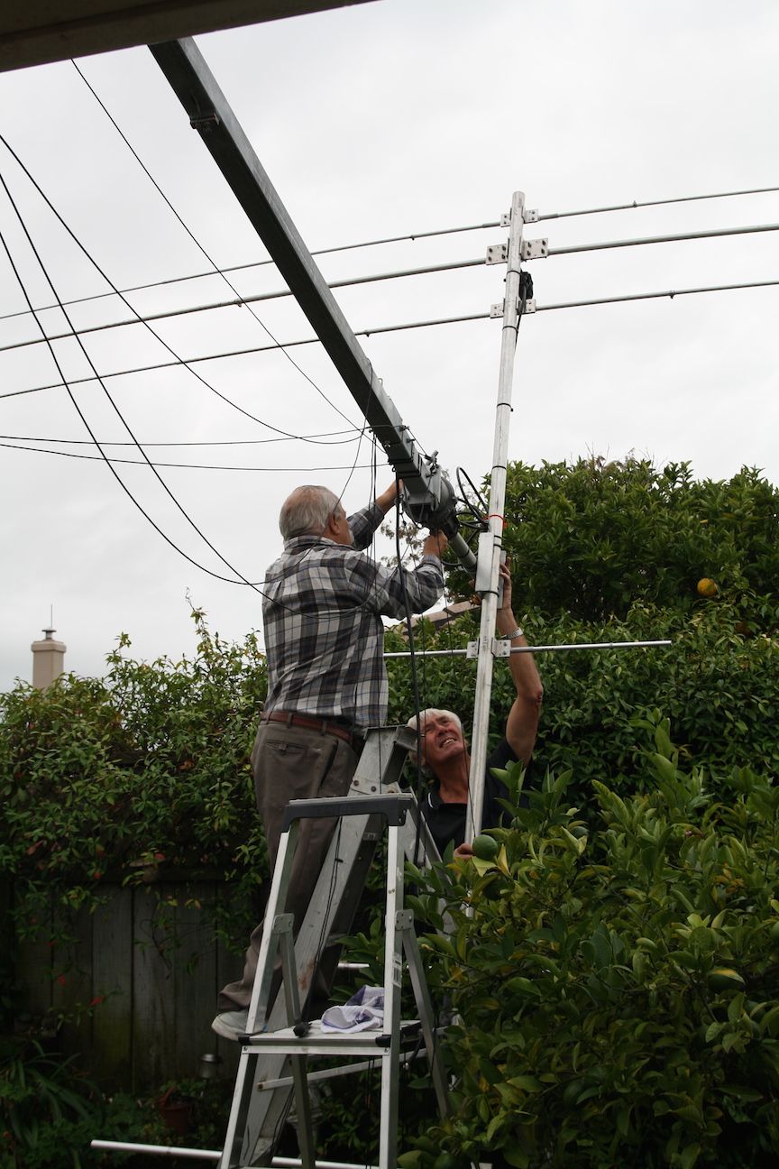
During the past week, the mechanical parts of the antenna were finally finished and it was ready to erect. Morrie ZL2AO and Karl ZL1TJ came over to give me a hand (More than a hand actually!) to pull down the old Hexbeam and replacing it with the new Tribander. The mast is a tilt over design that I built a few years and in very short time it was lowered over with a winch . A second winch allows the top section of the mast to be wound down about 20 feet into the lower section which makes life a bit easier. Karl and Morrie wrestled with the old Hexbeam until it was on the ground.
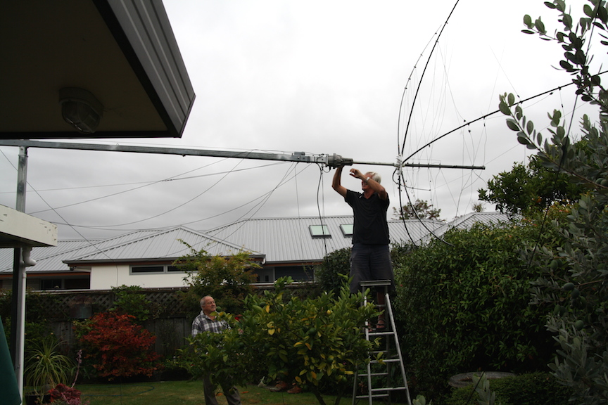
The Old Hex Beam being removed.
The Hexbeam actually failed because the plastic cable ties which held the hose clamp and wires to the fibreglass rods. I suspect that the failures occurred because of the 2400 hours a year of sunshine we get in this area of New Zealand.
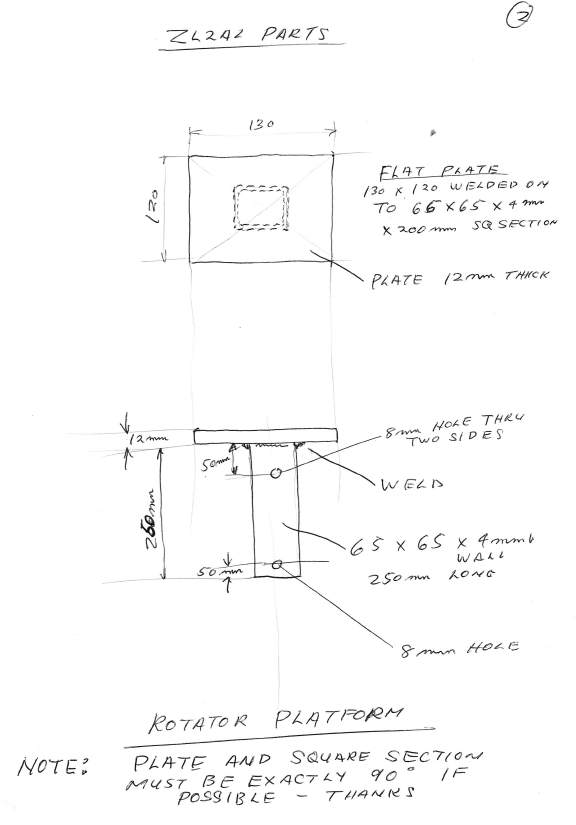
We assembled the rest of the driver elements and stood the 12′ mast up vertically to mount into the antenna rotator.
The 3 Driver elements in Place
All was going well so we cranked the mast off the ground and placed all the Reflector elements in place, did some final mechanical checks and it was ready to winch up to vertical. We cranked it up at about 25 feet and looked at the SWR and it was excellent on 20M but 500 Khz high on 10M and 200 Khz high on 15M. Various discussions centered around “we should do this with a calculator” and one was soon on the table with much head scratching etc. I made the call to wing it and pulled out the 10M DE by 4″ and the 15m DE by 2″ . Feeding the yagi through an 80 foot length of RG213 good quality cable showed the following results after the element length adjustments. 20 metres came in at 1:1 and 50 ohms at 14,152 Mhz The results were excellent with SWRs of 1.1 at 50 ohms on all 3 bands and just where I wanted it.
17M and 12M are a different story and need to be dealt with at the shack end. A few years ago I built a vacuum variable antenna coupler that will match almost anything. A few minutes winding turns counter dials and both 17M and 12m were able to be matched to the transmitter. NOTE: That does not change the SWR on the line. it simply allows you to use the antenna on those bands with power losses. In fact, 17M and 12M work rather well as a high dipole with unity gain. You couldn’t do the same thing with a typical trap tribander as the traps get rather warm working on bands they are not designed for.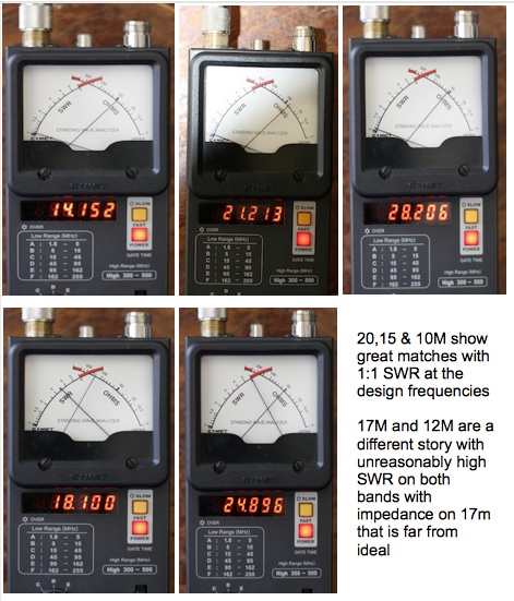 When you build an antenna from a patterned design you really cannot predict how it will behave in real life. An antenna analyzer doesn’t give you the whole picture either. You actually have to use it on the air to get a “feel” of how it performs. We cranked up the antenna into position at 35 feet and it was ready to have a listen. I was hearing a few signals on the bands but high noon in ZL is not all that exciting. Looking at the cluster there was a bit of DX around.
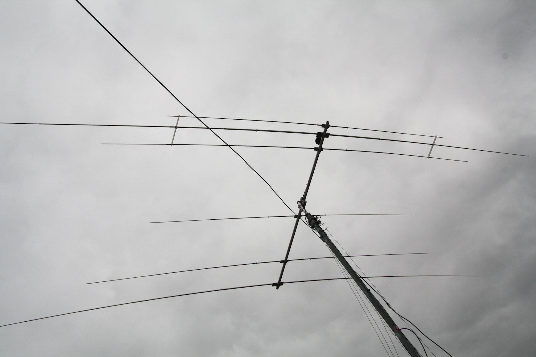
In place ready to go!
A few spins of the rotator on various sigs showed that the F/B looked good at a couple of S-Units and forward gain was just under an S-unit. It some very steep nulls off the sides. What I was experiencing is about what the design parameters had predicted for this antenna. I had a look at the cluster (around 0100UTC) and 9L1A was on 28,029 about 549 with a very smart op on the other end. With a rush of blood to the head I fired up the Alpha and gave him a call. The second call got my report and he was in the log and a big grin on my gob. Throughout the rest of the afternoon and evening I cruised the bands and made plenty of contacts at will. Even marginal signals were reasonably easy to work. My log is below.
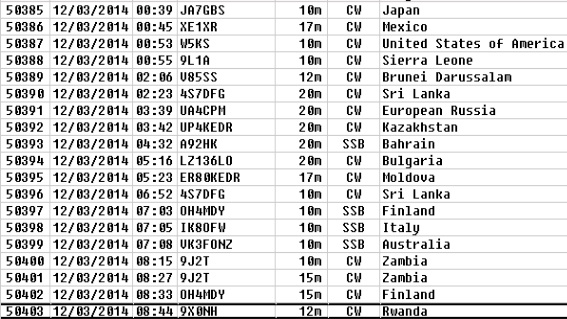
My Logbook for the Afternoon.
The antenna’s performance is very satisfactory. It is not a pair of stacked 204BAs. It was never intended to be. It is a light, easy to handle design that offers good performance on 20, 15 and 10M and is basically a high dipole on 17 and 12M.
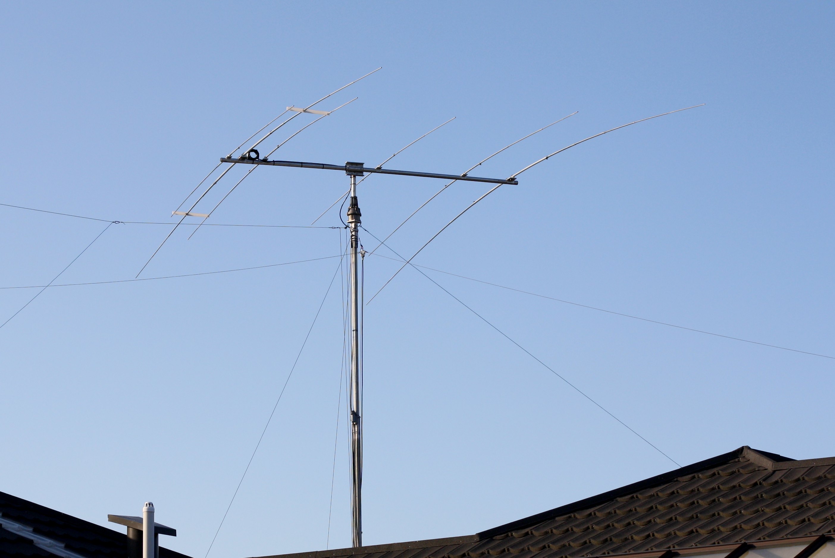
Finally up in place. Lean, Mean and NO TRAPs!
Nevertheless it works very well and has directivity. The joy of this antenna is that I will never have to worry about traps failing. It will also handle any power from my Alpha amplifier with ease.
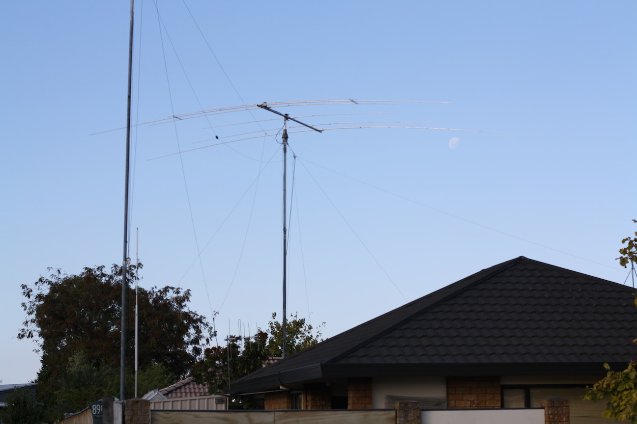
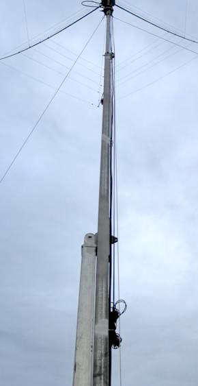
The Antenna in Place up 35′ The pole in the foreground supports my 30M full wave loop and the end of the 80M/40M Trap dipole
Since most of the materials were mostly salvaged from old alloy tubing and angles. Anything that I couldn’t find had to be commercially sourced the final cost was about 15% of a new Force12 C3S imported into New Zealand.
This is the end of the project and I am not sure what will follow next year.
73, Lee ZL2AL