There are a lot of “orphan” Icom power supplies that you see at the ham car boot sales and flea markets. They usually go very cheaply because they were originally purchased with the Icom 701 and the Icom 720. Both these models of radios have had problems over the years and their owners have moved on. Even though the radios are gone, the power supplies are heavy duty and built to last which is why there are plenty of them still out there. There are two models. The IC PS-701 was the original and it had a large transformer and very good filtering. When the IC720 was marketed, Icom sold the matching PS20 power supply and it is a newer, switch mode design. Even though many cheap switchmode supplies have a bad reputation, the Icom design was very well engineered with the switchmode components in a rugged diecast alloy box with a heat sink on the back. No RFI noise at all with the advantage of plenty of overload protection and excellent voltage regulation. The PS 701 is not really suited as it’s output voltage is 17 VDC unloaded and measures about 15 VDC fully loaded. It could be used if an on board regulator was installed. I have not looked at the internal circuitry of the IC-701 but suspect that the radio has in internal regulator. For our purposes I will only concentrate on the PS20.
I picked up a model PS-20 cheaply a while ago and thought that it would make an excellent power supply for any of today’s modern radios as the design is rated 13.8 volts at 20 amps. The cabinet is well constructed and it has a good quality speaker behind the front panel.
Conversion to a universal supply requires removing the very large DC cable from the back, moving the ground post, installing a pair of terminal posts and putting a switch on the front panel.
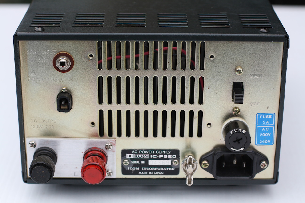
The back panel with the new 13.8 V terminal posts install and the Ground post moved to the right
The original design has one small slide switch on the back panel to sever the line voltage input. The only way of turning on the supply, other that connecting to the Icom radio is the ground the orange wire in the main DC cable via a second switch on the front or rear panel to activate the relay that puts line voltage to the unit. After removing the top and bottom covers the conversion as follows:
1) Cut the rear cable about 6 inches out from the back panel and peel back the outside plastic sheath. This exposes a red and black wires which is the DC output. It also exposes the orange control wire.
2) Remove the ground post and place it next to the AC input connector.
3) Make up a small alloy or steel plate as shown in the photograph with two terminal posts on the plate and mount it where the old cable hole is. You may have to do a pit of filing and trimming to make it all fit. I used 4 x 3mm screws to hold the plate in place.
4) Connect the red and black wires to the two posts.
5) Mount a main Off/On switch on the front panel. I used a small rocker switch and fitted it into the plastic front escutcheon to the left of the LED an the right hand side of the panel.
6) Connect the Orange wire to the switch and the other terminal to ground on the chassis somewhere.
7) Finished and ready to turn on!
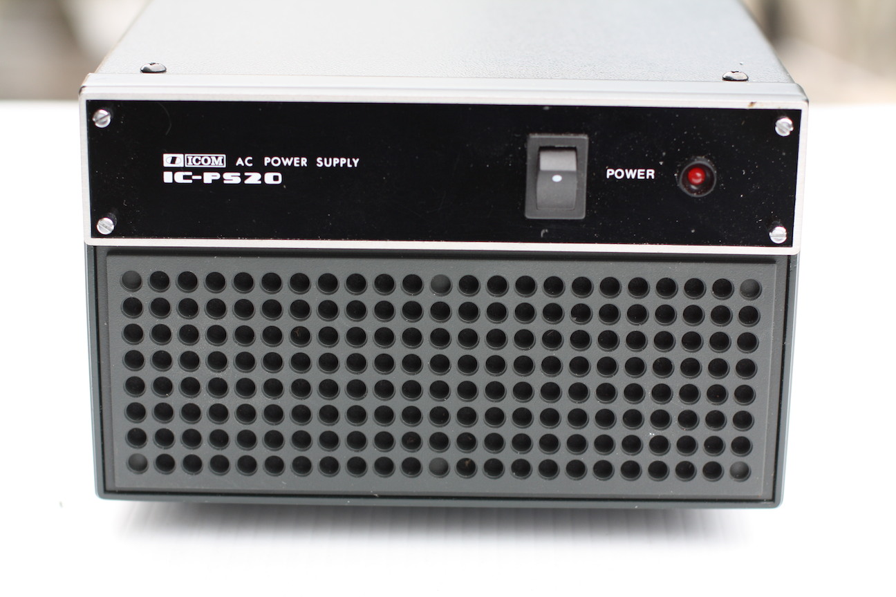
The new Line OFF?ON switch installed to the left of the Power on LED
It is a simple and easy conversion to a quality power supply for a very reasonable price. Photos are attached
73, Lee ZL2AL
Been absent from radio for some years. Bug bitten again so back to radio ! Picked up a brand new IC PS 20 Power Supply a couple of days ago and now into converting it following your excellent article on your website. Just one question (well for now ), The front panel seems to be about 1 inch thick, don’t know what it is made of, but how/where do I find a switch that can handle that thickness ? Regards Iain