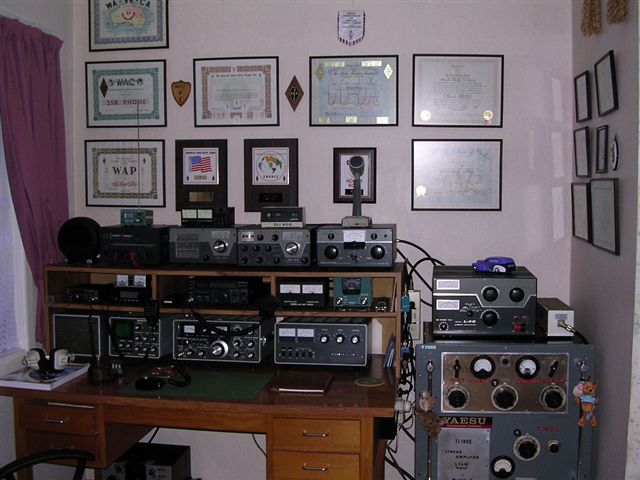
ZL1BOQ – Derek, Auckland

Was born in the North of Scotland in 1936, where I was educated in a boarding school. Every Saturday morning we were required to join a “hobby group”. One could do photography, metal work, carpentry or radio. I opted for radio, why I don’t know. After making a crystal set, which worked well, we went on to make one or two valve receivers. I was rapt. Right next door to the school was a Royal Naval air station, at Lossiemouth. Once a week we got the opportunity to go there and learn morse code, and procedure, plus we we shown how to operate and use Number 18 portable radios. After leaving school, we were required to do two years national service. I opted for the Navy, but as I was only going to be there for 2 years, I was not allowed to be a telegraphist. Instead an ordinary seaman.

After that, I had to work, got married, had children, and there was no time or money to pursue the hobby, so I forgot it. I came to NZ in 1970, got instantly employed, with a company car and expense account, and found I had a little money over, so got back into tinkering with old radios. Then I became an SWL for three years, when a neighbour, who was a Amateur, suggested I go for my ham licence, which I did.Got my grade 3 licence in 1973, grade 2 in 1974, and grade 1 in 1975. With a grade 2 licence, I was confined to 80m and 160m. Had no room for 160m antenna, but I did for 80m. In that 12 months of 80m only activity, I ended up with 89 countries confirmed. Shortly after that the 100 came easy. 5 years later, I brought the 5 Band DXCC award back from a visit to ARRL HQ. Three years later, I had all 200 CQ zones confirmed. 5 Band WAS followed in 1990. Then I moved out of Auckland to my present QTH, with retirement in mind. Only a quarter acre, but room enough for modest size antennas. in 2003 I found my self on ARRL Honour Roll. Nowadays, I just like DXing the lower bands, 40 and 80m, and a total change of direction, I now play around with Echolink via the computer, and working DX repeaters, in Berlin, Florida and Perth, W.A. It is hardly Ham radio, but quite enjoyable.

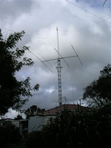
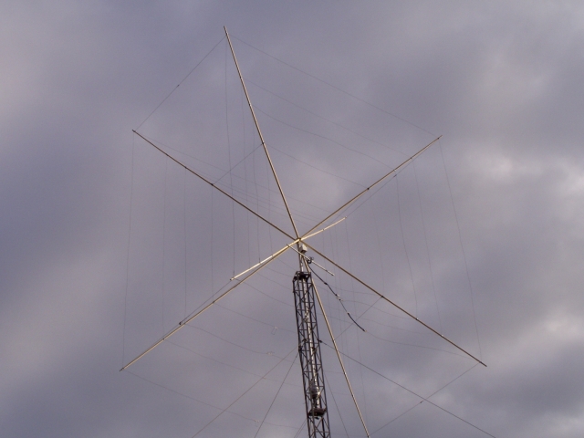
Was first licensed in 1974 as a grade 2. This allowed me to go on 80m 160m and VHF. When I upgraded in 1975, I had almost 100 countries confirmed on 80m. This inspired me to go on and attempt 5 Band DXCC. On my 44th birthday, I personally handed over more than 500 cards to the ARRL in Newington, back in 1980. 5Band WAZ followed in 1982, and 5 Band WAS in 1990. After that I just settled down to working the low bands mainly, where I am to be found now. In 2003, much to my surprise, I found myself on the ARRL Honour Roll. My station uses very basic antennas. They are easy to get going and to maintain. On 80m an inverted vee at 50 feet, on 40m a ground mounted vertical, with no radials; also an inverted vee at 50 feet, and on HF I use a run of the mill tribander at 33 feet.

I live in rural N.Z., just 30 miles South West of Auckland, with my XYL and cat.

73, Derek ZL1BOQ

Back to top^


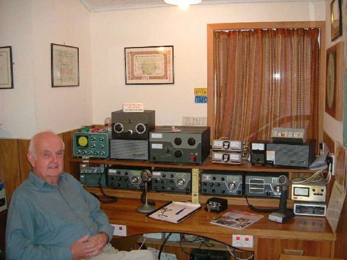
ZL2AFT – BRYAN ANDERSON, PALMERSTON NORTH

Over 60 years ago I heard about Amateur Radio while attending the PN Boys’ High School where I met the late Phil Howell (ZL3 ?) then science master, who introduced a small group of keen young students to the hobby after school one afternoon a week in the science lab. It was around that time local hams were receiving their gear back and permission to operate after World War 2. I was particularly thrilled to hear them on my home built “Hiker’s Two” with plug-in coils for the short wave bands. Later to be replaced by a 4 valve TRF receiver.

After High School, a carpentry and joinery apprenticeship, motorcycling, cars and social activities took precedence and it was 1954 before I finally managed the Ham ticket on my second attempt, CW and the eventual HF permit followed as did the home construction of receivers and transmitters from original AM into the SSB era. Many hours were spent in construction and I guess the separate SSB receiver and homebrew filter transmitter was the greatest challenge. I worked over 200 DXCC countries with this equipment. It was 1975 before I picked up a trashed Drake TR3 and after a week was on the air with that which started a ‘love affair’ with Drake gear which I still use daily. I must acknowledge the helpful advice I got during the homebrew  AM years from the late Gary McDonell ZL2SO and in SSB from many groups who gathered  in the evenings in those early years on 80m to help one another.

Bitten by the incurable DX chasing disease, required better antennas, operating all hours just to accumulate piles of QSL’s and a few more awards on the wall.

After 28 years of carpentry and back trouble I went back to night school for advanced qualifications, which opened new job opportunities, became a building inspector for a short period then finished my working years as a Polytech lecturer in Construction for 19 years.

48 years ago I married my wife Jill we have four boys who are all married and working in different parts of the world.

I have always tried to keep the hobby in perspective and not let it interfere with the more important things in life, none of the family have really been interested in the hobby as such. I think they feel one is enough. All but the first 3 years of my life have been spent at the same address, here antenna erection has not been a problem but who can guess what is ahead in the next sun spot cycle.

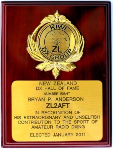
In 2011 Bryan was awarded the NZ DX Hall of Fame Award for his lifetime DX achievements. In 2009 Bryan also became one of the very few ZLs who achieved ARRL DXCC No. 1 Honour Roll status when he finished working the last one on the list of 341 current entities. Licensed in 1954, Bryan has a long history of working DX with his own homebuilt and antique Drake equipment and had over 200 countries confirmed by by 1975. mostly with antique Drake equipment. He has given outstanding service to his local radio club and assisted many ZLs to achieve DX in the pile-ups.


73, Bryan ZL2AFT


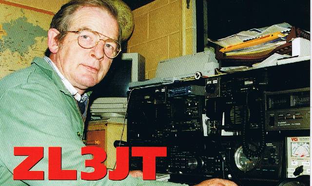
ZL3JT – Duncan McMahon, Christchurch

I have always been interested in radio since the age of 5 when my old man tuned up his broadcast Band program on Sunday afternoons. I hankered to play with that tuning knob, but God help any stupid kid who dared to touch it! Relief came when I built myself a crystal set a few years then later I got a real radio with valves. I enlisted in the RNZAF at 16 years of age. They wanted me to pursue a career in avionics but I became an engine mechanic. My career lasted 21years and I was awarded the B.E.M. for my services. By 1970 my hobbies included hunting and fishing, model railways and hockey, gaining a New Zealand Hockey Umpire” grading.

I was inspired back into the radio world by an incident out fishing in the back country of Nelson. We needed radio communication and I then purchased a CB set. I got involved with 3 other guys who became amateurs in 1989-90, two of them are now silent keys ZL3ARM and ZL3TBO. I enjoyed working DX on CB and when SSB and 40 channels came on the scene in 1986, a new world opened but I found out that I was not supposed to be doing this but I loved it. I remember my uncle, Bob Dixon, (ZL3JT) and sitting on his knee at 6 years old while he talked to the World.

I sat the exam in March 1990 at the age of 45 and was allocated ZL3TCD. Morse code was a problem for me but passed at 6 wpm and later passed the 12 wpm test with Noel ZL3QC and became ZL3JT. I was on top of the World with a new shack, a new tower, a new antenna, new Kenwood TS690SAT.

I met ZL3JU, ZL3RG, ZL3ARK (now ZL3RK)…we set up a “DX watch net” on 70 cm simplex. ZL3AFT joined us… we worked DX and in 10 years gained DXCC Honour Roll. Paul, ZL3HAG, (DL4BCG) brought a single paddle electronic keyer and left it with me. That night on 40m I worked 12 twelve DX stations…it took about the same time as Paul worked 120…but It was wonderful, wonderful! I heard 3D2RW running pile ups…Ron was just the guy. I wanted to be like that.

Currently, my station consists of a Kenwood TS590, Tokyo High Power HL1.5Fx and my Cushcraft A3S up on a home brew tower at 42 feet Recently, I purchased a SteppIR 3 Element multiband antenna to enable me to work the WARC bands. I have almost “been there, done that” with DXCC Honour Roll mixed 333/335, DXCC CW 320, DXCC phone, DXCC RTTY, EQSL and DX100 (first station in the Southern Hemisphere). Even the magic band got a hiding during the last cycle with 49 confirmed, with the TS690 and only 50 watts I made the first ever 6M PSK31 contacts to Australia, Japan and USA. (World Record 6M).

All this is possible with my very understanding wife Briar. Our two daughters have long left home, and are busy raising our grandchildren. I have a great advantage over others who would aspire to work DX. I am self-employed, work from home and my radio shack is part of the workshop so I can monitor the DX frequencies almost all the time.

73, Duncan ZL3JT

DX Windows, High power and Good Manners

DX Windows,  High power and Good Manners

There has been a debate going on the reflectors about high power and the abuse of the rules governing each country’s power regulations. The ZL limit has now been increased to 1000 watts and our signals have the ability to be easily heard on the other side of the planet

A well known and respected DXer had this to say;

“I hear what you are saying about high power and you probably are correct in your thinking. But I see very few of these super high power alpha male hams on the DXCC Honour Roll or see them actually emerge with an intact reputation after a lot of years of doing what they do. High power doth not maketh the complete amateur. In fact it does the opposite. Power corrupts. Witness the reputation of the Alpha male “DX window terrorist” Italian on 14,195 month after month. He runs super high power, has a great antenna system and drives the DXing fraternity mad by sitting on top of major DXpeditions and transmitting a string of foul abuse.

He revels in the publicity given to him on the DX Clusters which is why he continues to do it. He is the DX equivalent of a repeat offender drunk driver. He really doesn’t accomplish a lot except contribute to the profits of his electricity supplier and enrage the rest of the world’s DXers. We all know him. I am not talking about the odd amateur inNew Zealandthat runs a clean kilowatt amplifier and there are many that do. Doubling your power output only gives you 3 db on the other end over 500 Watts so it’s hardly worth worrying about. They have to live with their own reputations.

I actually am not worried about the high power terrorist wannabees. They create their own reputations somewhere between a bad smell and a loathsome creature that crawls out from under a kicked over rock. I can live with them as they are few and far between and do not represent anything sane in Amateur radio.

I do worry, however about the VKs and ZLs that show lack of courtesy by rag chewing in the “DX window” around 14,195 Khz. They simply call a CQ DX (which is the worst way to try and snag a rare DX station!) in the window and when answered by another VK, ZL or USA station and carry on a long irrelevant QSO totally unaware of what maybe under them. And of course they don’t have DX cluster on the screen in front of their noses. You would think that most hams around the world would know that the 20M and 80M DX windows are pretty special and DXpeditions generally use those two arenas.

I often hear a VK and a ZL carrying on 14,195 comparing signal reports, transmitter power etc while all the time a Rare DXpedition station was underneath them. They didn’t have a clue that at that particular time thousands of DXers were cursing the very existence of VKs and ZLs. Of course their excuse would be “I didn’t hear anybody” The answer to that is that just because you can’t hear them, doesn’t mean that they are not there and you are not interfering with hams in some other part of the world trying to work them. I am sure that if I confronted either of these gentlemen, their excuse would be “I called CQ and was answered by a VK and he is DX to me. “Yeh right”.

In this particular case it was mentioned to me in an email from a mate on another continent about the operating habits of a few VKs and ZLs in the 20M DX window. I have to agree. The same thing happens in the 80M DX window from 3780 – 3800 Khz. I care about our ZL reputation in the international DX community. In actual fact we rate extremely highly internationally and I would like to keep it that way.

If you call a CQ DX in any DX window and are answered by a “local” VK or ZL then move off the frequency and leave it for your fellow DXers. It’s easy to say “Down five” or Down ten” If you call and work a rare DX station, be aware that there are a lot of other guys that are listening to you waffle on about your family and dog while waiting to have a go at the DX station.  A bit of knowledge and common courtesy should prevail. It’s just good manners!

73, Lee ZL2AL

Back to top^

Do All the Digital Modes, Cheap!

Do All the Digital Modes, Cheap!

By Scott N4ZOU

The solar cycle is winding down and the higher HF bands get poorer by the week. Even the 20-meter band closes down pretty early in the evening, sometimes even the afternoon! You go to the digital modes area where you might find a few PSK-31 stations but copy is really poor with the band in and out. You drop to 40 meters and try that band but between the high noise level and the SSB DX even if you managed to find another operator there you had a very hard time understanding what the other station was sending due to the lost words.

If you have been around a few years you remember using Pactor in ARQ to get your message across even while the band is in and out for short periods or the noise is bad. If you have been a digital operator for 10 or more years you remember how great Amtor in ARQ was for getting that text across what some would assume was a dead band, you could not even hear the other stations Amtor noise in your speaker if you had it turned up but still the text was flowing, a little slow with lots of errors and re-sends but it was still working.

When PSK-31 and the other digital modes used with a computer sound card started the 20-meter and higher bands was just beginning to come alive with the solar cycle starting to rise. A lot of operators that had never used digital modes tried out the new sound card modes and even some of the old modes that the sound card could handle like RTTY and found them to be fun. Most of us already doing digital modes also enjoyed them and so a lot of the terminal controllers like the PK-232, KAM, and MFJ-1278 got taken out of line and an interface for a computer sound card that you already had got put in line. Some of us sold their terminal controller’s thinking that it was now outdated or put it in the closet to collect dust with some other out dated or boat anchor gear. I was guilty of that!

A few months ago when I figured out that the only modes that were going to allow me to operate and still have fun at it on 40 and 80 meters was Amtor and Pactor in ARQ error correcting mode. I dug out my old PK-232MBX and hooked it up and tried it out on RTTY mode on 20 meters and it still worked! I started looking around the band and found John W2LWB calling CQ in FEC Pactor. I entered the command to link to him and got it going and had a great time with a long chat that was error free. Then I remembered how fun old Amtor was and switched to FEC Amtor mode and called CQ with no luck at all for several hours. Then it hit me! Amtor was considered so out dated no one would even remember what the 100-baud signal would sound like and would never call me in that mode much less start an ARQ link.

I went back to Pactor mode a few weeks and also did a lot of RTTY operating. I ran into John K3KXJ in RTTY mode and noticed that in his brag file that he was running an old PK-232. So when it was my turn to key down and type I asked if he would like to switch to ARQ Amtor mode as the band was starting to get poor. We did switch modes and got the link going right off and we both had a great time chirping away. That’s when I built a interface box that would allow me to switch between the PK-232MBX and the computer sound card with just one DPDT switch on the front of the box containing all the required circuits for matching the audio between the sound card and the transceiver. It worked out very well. Not only did I have the modes in the PK-232MBX not available for use with the sound card but also with the flip of one switch I have access to the sound card modes! You can download a PDF format file containing all the information on building the interface box at http://www.geocities.com/n4zou/files/tnc-psk.pdf.

Now When I call CQ in RTTY mode I include that I can take Amtor links as well and give my Selcal Amtor ID used in starting a link. This works and I do get many ARQ Amtor links. You can read all about it at http://www.geocities.com/n4zou/files/amtor.pdf.

The old band plan for Amtor was from 14.065 to 14.085. Today 14.065 to 14.080 is used with Pactor MBO stations and Keyboard QSO’s and also PSK-31 is used around 14.071. This leaves 14.080 to 14.085 for shared RTTY and Amtor operation. All the bands except 10 meters, 160 meters and the WARC bands follow the same general agreements as to where and what mode is used.

Now we get to the interesting part of this story. Just how do you get on ARQ Amtor and Pactor modes without an expensive TNC? With a simple and cheap Hamcomm style modem also known as a Volksrtty modem connected to a RS-232 comport on your computer and run a DOS based program called Hamcomm 3.1 or Terman 93. I ran into Bill K0CDJ that had purchased a kit called a Volksrtty modem and was trying to get it to work in ARQ Amtor and the Hamcomm 3.1 program. We could start the link but after a minute or so it would start producing errors and then do a re-link to start sending text across again. It turned out to be a timing problem, which was corrected by monitoring the ARRL digital bulletins sent in FEC Amtor mode and compensating for the clock in the computer. After Bill corrected the timing problem we linked in ARQ Amtor mode a few days later with no errors! Bill said that he also has made several Pactor 1 links using the same Volksrtty modem and the Terman 93 program that also does Amtor and RTTY. We tried it and we linked in Pactor 1 and it did work very well. The only downside to using these programs is that they must be run under DOS.

Due to the critical timing required in these modes no other programs can be running in the computer so you can’t even run them in a DOS window while still having Windows running. If any program grabs CPU time while your ARQ linked to another station the link will shut down. When the link is running it’s like a chain driving a camshaft in an engine. If another program grabs CPU time then the chain just jumped a few notches and the engine dies, as the ARQ link will. The good part of this problem is that an old 386 and higher computer will run these programs just fine.

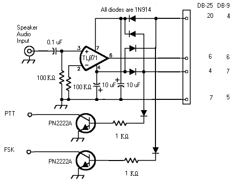
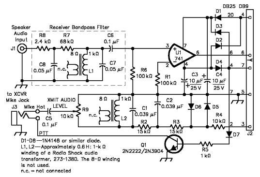
As no sound card is required you could find an old 386 Laptop computer for a few dollars and use it as a dedicated terminal for RTTY, Amtor, and Pactor. The Hamcomm or Volksrtty modem can be built for only a few dollars and will cost less than most sound card interface box’s using expensive isolation transformers. The interface consists of a 741 op-amp or for better performance uses a TL071 (T L ZERO seven one), PN2222A (2N2222) transistors, resistors, capacitors, and 1N914 diodes. The optional Band pass Filter is worth adding if you can’t use narrow filters suitable for FSK signals in SSB mode. I order all my parts from www.mouser.com. You can order by Internet, phone, or mail and use a credit card, check, or money order. The modem can be built several ways, FSK, AFSK, and optional audio filer included.

I just had to build one myself and try it out after talking to Bill. I built a really cheap one for use with my ICOM IC-756 PRO II. I already had everything required but even new parts from Mouser would only be $1.60! I did not use any audio filters in front of the TL071 as the DSP RTTY filter in the PRO II takes care of that. I also did not build the AFSK circuit, as you must use FSK in RTTY mode on the PRO II. The DTR pin on the RS-232 comport is for keying the FSK pin on the transceiver. RTS is used for the PTT circuit. This is very nice as it allows you to use the same comport for keying the transceiver if you also include circuits for use with a sound card.

If you can’t use FSK with your transceiver you will need to build a simple AFSK circuit that uses the same comport. You can leave off the FSK circuit if you like. This will connect to the microphone input pin or the audio in pin on the back of the transceiver.

Below is a schematic of a Basic + Hamcomm interface by K7SZL and is well worth the cost of the few extra parts required.

Using SSB mode on the transceiver will allow lots of noise along with the FSK signal to enter the OP-AMP so unless you can use a narrow filter in SSB mode the optional Receiver Band pass Filter should be built and placed between the transceiver audio output and the OP-AMP input to get the best performance from your modem. Here you could also use an external audio filter for the audio input to the OP-AMP such as an Autek Research QF-1A, Vectronics VEC-884, Timewave line of DSP Filters and even MFJ has Audio filters that can be adjusted to work just fine. If you already have something like one of the above products go ahead and use it, it can only help. Adjustment is easy, just bring up Hamcomm and the tuning display and find a station transmitting an FSK signal. Now adjust the filter so that only the Mark and Space tones show on the display.

All the circuits are non critical and can be built using dead bug style construction. I used a solder less breadboard mounted in a metal enclosure with different style connectors mounted on the back and a DPDT switch mounted on the front several years ago. This allows me to build different experimental circuits with little effort. I have been using this box for my TNC and sound card setup. For this project I un-plugged the sound card parts from the board and plugged in the Hamcomm parts. As I already have a TNC I don’t really need the Hamcomm modem so later I will be re-installing the sound card interface circuits. If you want you can order a circuit board from FAR Circuits that is designed for not only Hamcomm and Terman 93 but also other software programs.

The link to the ARRL article is http://www.kiva.net/~djones/n9art.pdf. This interface not only has the Hamcomm modem it also includes circuits for interfacing a sound card and the modes available for that type of modem such as PSK-31. If you do not already have a multi-mode TNC this is the way to get on all the modes. Mouser has prototype boards but there expensive. In this case a trip to Radio Shack might help out with the circuit board and enclosure. You could make it like I made mine and be able to experiment with different circuits and parts at a slightly higher cost or solder everything down and make it as small as you can for use with a Laptop and portable operation. You could even place it inside your computer! The back side of a comport connector could allow you to make your connections there and mount the entire project inside the computer and only have a transceiver connector mounted on the back.

For ICOM transceivers a DIN-5 plug and aMIDIcable would work great. Ten-Tec sometimes uses RCA jacks so if you have that setup RCA jacks mounted on the back of the computer case would allow standard cables for that. KAM TNC’s use a DB-9 connector on the back for connecting to a transceiver. You could remove the ribbon cable from the back of the comport connector and use it to connect to the modem and then go from the output of the modem back to the DB-9 connector and wire it up the same as the KAM. This would allow using KAM cables in your setup to the transceiver. Just figure out what would be the easy and cheap way to go with your setup.

Before you order the parts and build your interface you might want to use and older device that connected to computers in the past like the C-64. You might have one in the closet already! Included but not limited to this list is an AEA CP-1 or CP-100 computer patch. They are also cheap at anywhere from $10 for a CP-1 to about $20 for a CP-100. These are not real terminals but demodulators that do the same job as the simple Hamcomm modem but in a much better way. They have internal filters setup just for the mode your going to use and tuning displays.

They also use there own power supply and do not use power from the comport. Check and see if that old RTTY box in the closet works the same way. One thing to check is if the computer patch or RTTY box has an RS-232 port installed. Most of them only have TTL and so you must build a TTL to RS-232 converter to use them. Also the RS-232 connections are not standard, you cannot use a standard serial cable to connect them to your computer. The following link will take you to a good site where you can get the information you need to use the computer patches with Hamcomm or Terman93 http://www.klm-tech.com/technicothica/. From what I understand some Timewave DSP filters include FSK mode modulation and de- modulation circuits. You will need to check this and if true you might already have every thing you need. I don’t have a manual for them and they’re not available for download so I have no idea how they work.

Now you have no excuse not to get on all the available digital modes including the ARQ modes and not be limited to just the sound card modes or just a multi-mode TNC. Here are links to the software and some sites that also have lots of information on the Hamcomm and Volksrtty modems and software.

http://www.cqham.ru/volksrtty.htm

http://www.g7ltt.com/hamcom/hamcom.htm

http://www.g7ltt.com/hamcom/enhanced.htm

http://w1.859.telia.com/~u85920178/use/hc-00.htm

http://www.wd5gnr.com/hamcomm.htm

http://www.baycom.org/~tom/ham/terman93.zip This is the link to download Terman93.zip

http://www.pervisell.com/ham/hc1.htm Download the Hamcomm 3.1 software from this link.

Here is a Parts list from Mouser with Mouser part numbers. If you order all the parts including the optional audio filter and FSK circuit the total cost is only $8.40. I did not include a circuit board, cable, and enclosure as this depends on how you will want to use the modem and if you order the FAR circuit board and build the dual Hamcomm and sound card modem.

Part Description Quantity Mouser Part # Price
U1 TL071CN 1 511-TL071CN .40
Receptacle DB-9 pin 1 156-1309 .66
Capacitor .1uF 2 140-PF2A104G .63
Electrolytic 10uF 2 140-L25V10 .16
Capacitor .039uF 2 140-PF2A393G .56
Capacitor .05uF 2 140-PF2A503G .56
Resistor 100K 2 30BJ250-100K .22
Trim pot 10K 1 323-409H-10K .61
Resistor 15K 2 30BJ250-15K .22
Resistor 10K 1 30BJ250-10K .22
Resistor 1K 1 (or 2*) 30BJ250-1K .22
Resistor 68K 1 30BJ250-68K .22
Resistor 2.4K 1 30BJ250-2.4K .22
Diode 1N914 7 78-1N914 .03
Inductor* 680uH 1 (or 2*) 580-22R684 .58
Transistor PN2222A 1 (or 2*) 512-PN2222ABU .11

* FSK mode requires two PN2222A transistors and two 1K resistors.

The Radio Shack audio transformers shown in the K7SZL circuit should not be used. The quality of these transformers varies and you can no longer expect to be installing a .6H inductor. If you build the Audio filter order two of the 680uH inductors to replace the Radio Shack transformers.

511-TL071CN Data sheet link http://www.st.com/stonline/books/pdf/docs/2296.pdf 512-PN2222ABU Data sheet link http://www.fairchildsemi.com/ds/PN/PN2222A.pdf

Back to top^

171 Metre Loop Antenna

             A 171-MeterLoopSkywire Antenna – by Heinz KB8VIP and Mary KC8SXL

First of all, why 171 meters? Has the FCC opened up the top of the AM broadcast band to amateur PSK-31 transmissions? No, but the HF PSK-31 sub-bands are at least partially related harmonically and a length of 171 meters (562 feet) makes a loop skywire antenna a good fit for most of them. Full-wave loops have won the accolades of amateurs ever since they were first described in 1985 by Dave Fischer, W0MHS (QST, November 1985; The ARRL Handbook). Our antenna, an irregular pentagon strung from trees, is fed directly with 50-ohm coax and covers most of the PSK-31 sub-bands from 80-10 meters with a maximum SWR of about 4:1 without using a tuner or a balun. Its high gain and low radiation angles facilitate working DX.

Designing and modelling the 171-meter loop skywire

Our current operating interest is low-power PSK-31 on a number of HF bands. Our objective at the outset of this project was an antenna that would:

  • Provide superb reception.
  • Cover multiple amateur bands.
  • Be relatively omni-directional.
  • Have the low radiation angles required for DX.
  • Be coax fed.
  • And, oh yeah, be cheap.

After some research, we decided that a horizontal loop seemed like our best bet. We are fortunate in having relatively few space limitations at our rural Coshocton County, OH QTH. Our major constraint was the position and height of appropriate trees from which to hang the antenna.

As a start, the resonant length in feet of a loop antenna can be approximated by dividing 1005 by the frequency in MHz. While it’s certainly not necessary, we simulated the loop using the antenna modelling program MMANA. In addition to optimizing the length, models can predict the SWR, gain, angle of radiation and directional properties of an antenna. Adjustments can be made for antenna height and ground type. Antenna models are similar, differing mostly in input-output features. Most use the “method of moments”; which means the model calculates one antenna segment after the other. MMANA is freeware and can be downloaded from www.qsl.net/mmhamsoft/mmana/index.htm. A demo version of a commercial antenna modelling program EZNEC can be downloaded from www.eznec.com.

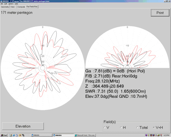
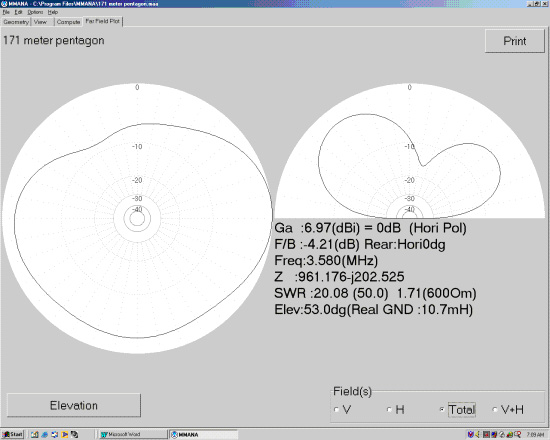
For the geometry defined by the location of our trees, we arrived at an optimum total length of 562 feet consisting of five segments of 167, 95.5, 114, 112 and 73.5 feet. The gain, angle of maximum radiation, calculated SWR and actual SWR of the loop for the important PSK-31 frequencies are summarized in the table.

Frequency (MHz) Gain (dBi) Angle ofMaximum Radiation (deg) Calculated  SWR ActualSWR
3.58 7.0 53 20.0 5.0
7.07 10.6 35 9.1 3.1
10.14 5.0 73 33.0 3.1
14.07 12.4 14 10.5 3.0
18.10 11.2 11 24.5 4.0
21.07 9.2 30 32.3 3.1
28.12 7.8 37 7.3 3.0

It’s important to remember that all antenna models are simulations; they are not the real thing. Simulators are a great way to learn to fly an airplane. But you can’t actually fly from New York to Paris in a simulator. It’s the same with antenna simulations. You’ll learn a lot about the antenna’s anticipated performance, but you can’t actually have a QSO. They’re the “next best thing to being there” and can be a lot of fun especially when the sunspots aren’t cooperating. More about the antenna’s actual performance later…

Hanging the 171 meter loop

The antenna is made of insulated number 14 stranded wire from the local home products outlet. Do not assume that these nominally 500-foot rolls of wire will contain 500 feet! Ours was 18 feet short. The wire is threaded through five “dogbone” insulators connected to the support ropes with 24-inch 125-lb test bungee cords. The support ropes are polypropylene agricultural hay baler twine. This rope is UV stabilized, has 240-lb knot strength and is available from farm stores for about twenty dollars per 6500-ft roll. The only limitation is its low abrasion resistance. Make certain the rope is not pulled back and forth over a tree limb in the wind.

Support ropes were put in place using a slingshot and spin casting rod and reel. A lead sinker, painted orange for visibility, was attached to regular nylon fishing line and launched over the appropriate tree limbs. The sinker was removed and the nylon line was used to pull mason’s twine back to the launch point. Finally the mason’s twine was used to pull up the baler twine. Don’t attempt to skip the mason’s twine step. Fishing line is not strong enough to pull up the heavier baler twine.

Manhandling almost 600 feet of wire is a tad more challenging than dealing with a 40-meter half-wave dipole. To measure it, we pounded two stakes in the ground exactly 100 feet apart and then walked sections of wire past the stakes marking the sections at the 100-foot intervals with masking tape. The completed loop with attached coax was laid out on the ground. The five insulators were threaded on and put into position. Bungee cords were attached between the insulators and the support ropes, which were raised incrementally into the trees. The entire procedure took the better part of a day.

Several accounts of full-wave loop antennas state roughly, ” It was the greatest antenna I ever had until it fell down for the umpteenth time and I got tired of fixing it.” After two initial breaks due to wear against the tree limbs, our antenna has successfully survived a rather brutal winter and spring here in eastern Ohio. Anticipating breaks, we first put in place permanent “lifting” loops of baler twine reaching from the ground to the support limbs. These loops are used only to raise the actual antenna support ropes. Not being under tension, the lifting loops never wear out and you never need to get out the slingshot again if the support ropes break. Having five support trees rather than four facilitates repairs since more of the antenna remains airborne when a support rope does break. In addition, the probability of all of the trees pulling against each other in a storm and tearing the ropes or wire decreases as their number goes up. Keeping the antenna completely free floating in the insulators also minimizes breaks. The wire can re-establish equilibrium when stressed in a storm. This can shift the point where the transmission line is attached, but with no detectable effect on performance.

The proof is in the PSK-ing

As shown in the table, actual SWR, as measured by both our ICOM IC-718’s internal meter and an auxiliary meter, are significantly lower than predicted by the model. At 20-30 watts output, the transceiver shows no sign of reducing power. Our expectation of needing to use a tuner with the antenna was pleasantly eliminated. On the other hand, the predicted high gain and low radiation angles are supported by our operating results.

Loops are known to be great for receiving and this one’s no different. Compared with our other PSK-31 antenna, a 20-meter dipole sized for 14.07 MHz, reception with the loop is almost always at least one S unit better. Noise levels are very low. Short-wave broadcasters, Dominion Observatory Canada at 3.333 MHz and the 60 kHz time signals from WWV all come in well. Even CB transmissions from the truckers on the expressway five miles away come in loud and clear on the IC-718. Some day we’ll have to buy a CB radio and see if we can talk back. Just kidding!

The antenna is great for receiving and “if you can hear `em you can work `em”. PSK-31 stations in Europe,South America, Japan and Africa have been worked regularly. Contacts have been made 80, 40, 30, 20, 17, 15 and 10 meters. Not requiring a tuner makes band switching a breeze. In the MMANA screen prints, the calculated directional patterns have an egg-dropped-on-the-floor look, but are in reality omni-directional. It’s noteworthy that the average height of the antenna is only 35 feet. An 80-meter dipole at this height would radiate most of its energy straight up, but this antenna’s angle of maximum radiation is a DX-friendly 53 degrees at 80 meters.

The simulations suggest that a better impedance match could be achieved on some bands by feeding the antenna with 300-ohm twin-lead or by using a 4:1 balun with the 50-ohm coax, but at the power outputs we’re interested in that’s really not necessary. The lengths of the individual segments could be optimized to favour a specific band of interest. We certainly plan to do some tweaking, but for us this may just be the perfect PSK-31 antenna – for less than fifty bucks and with a lifetime supply of baler twine left over. 

Back to top^
 

Why Vertical Antennas? – 6Y2A Contest Team

Why Vertical Antennas?

The selection of using vertical antennas was not a natural choice. The “conventional wisdom” for contest-expeditions and Dxpeditions was to use Yagi antennas when ever possible, regardless of the height. “Conventional wisdom” would tell you that a 3 ele Yagi at 25′ to 30′ high on 10m, 15m, or 20m would be the correct (if not only) choice.

When first researching our antenna selection, most of the major contesters in the USA said that the Caribbean stations ALWAYS came in at a high angle. Again, more “conventional wisdom” indicating that a low Yagi would be the best choice from Jamaica.

When we were running our propagation programs, the team noticed that the take off angle to the USA was actually a 1-hop LOW angle. Not the high angle that most people indicated. Which was right: conventional wisdom or the computer models?

In our first trip to Jamaica during the ARRL DX CW contest, the group used a blend of antennas:

  • Verticals for 40m -160m
  • Both a horizontal Yagi and vertical array for 20m
  • Yagis for 10m and 15m.

The use of Yagis on the high bands seemed appropriate, as we would elevate them between 0.5 and 1.0 wavelength high. The computer models indicated that the Yagi should perform OK.

While in Jamaica before the contest, the team ran extensive tests with the 20m 2 ele Yagi (45′ high) and the 2 ele parasitic vertical array. The results were astonishing: of the hundreds of tests, there were only a handful of times the horizontal Yagi was better than the vertical array (and only by a small margin).

Most of the time the vertical array was 2 S-units stronger than the horizontal Yagi! In fact, there were many occasions when a signal was an honest S-9 on the verticals (on the FT1000-MP) and S-0 and almost unreadable on the horizontal Yagi. This extreme difference can only be attributed to a signal arriving at a VERY low angle, where the Yagi had little gain.

These results, amidst many additional months of research, convinced the team that verticals by the ocean were the only logical choice for competitive contest-expeditions.

The following graphs were created by N6BV of the ARRL:

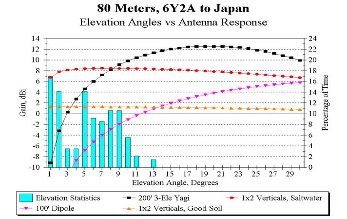
The first chart (below) shows an analysis of the take off angles from 6Y2A to Japan on 80m compared to various antenna choices.

First, let’s look at the vertical bars (light blue). This is a statistical grouping of all take off angles between 6Y2A and Japan over all times of the sunspot cycle, over all months of the year, and over all conditions. The data is displayed in the percentage of times a signal will arrive at a given angle: right X-axis is the % of time, and the Y-axis is the take off angle.

Thus by looking at the first bar on the left, we can see that on average, signals will be arriving at 1 degree take off angle nearly 17% of the time. In fact, you can see that ALL signals will arrive at or below 13 degrees on all occasions. Those are very low angles!!

Overlaid on the take off angles are the elevation-plane analysis of standard 80m antennas. Lets look at the 80m dipole at 100′ (pink with inverted triangles). By most standards, this is a very good antenna. But you can clearly see there is little gain at the low angles.

Next, look at the 1 x 2 verticals over good soil (2 ele parasitic vertical array). This antenna provides you with a large improvement over the dipole.

Now lets jump to the “ultimate” 80m antenna: a 3 element full size Yagi at 200′!! There aren’t many of those around, and who ever uses them will rule the band! (based on conventional wisdom). The 3 ele Yagi really does a great job over most arriving signals.

But let’s finally look at the 1 x 2 verticals over salt water (orange with circles). We can see that the verticals have a large advantage over the 80m Yagi at the very low angles. In this example, the verticals have a 16 dB improvement (3 S-units!) advantage over the Yagi. On the higher angles, the vertical still performs well. Overall, we believe the 2 ele vertical array over salt water is a better all around antenna than a full size 3 ele 80m Yagi at 200′!

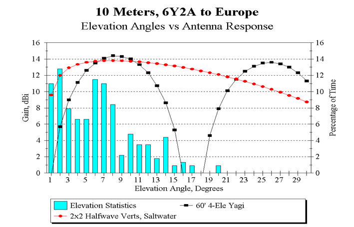
The next graph examines the take off angles on 10m to Europe. The reference antenna is a 4 element Yagi at 60′, an excellent contesting antenna. You can see that the 10m horizontal Yagi still does not cover the very low angles, and there is a null where there are still many signals arriving.

The comparison array is the 2 x 2 vertical array. The 2 x 2 verticals match the peak gain of the Yagi, but also offer excellent coverage over all arriving angles. Did we say that verticals by the beach rule!?

The team has done extensive modelling to all areas of the world on all bands, the results are typical of the examples above: Vertical arrays over salt water are very competitive antennas.

Learning the Morse Code

Learning The Morse Code from the NZART Website by Gary Bold ZL1AN

key

There are three words that help you to learn morse code:

PRACTISE, PRACTISE, PRACTISE

To help you get the practise, here is Gary Bold’s free teaching software for learning morse for PC only, Windows 95/98 XP Vista and above systems at 549 kB in size.

Morse Teaching Software Filename: 
-instal-teach4.exe
-549 kB

Last update 04-February-2008

Its just like learning to ride a bicycle. It’s far better to learn the Morse symbols by sound, and not sight! It is not a good idea to memorise a written table. Get an experienced Morse operator to send characters to you with an audio oscillator, saying each symbol after it’s sent. You want to recognise the symbols by their sound. Tapes are available which will teach you to recognise the symbols by their sound.

The ideal method to learn Morse is by use of a computer. Morse code training programmes are available –– see below for one of them.

Learn them at the same time–if learned later, they take a long while to become as familiar as the symbols. Learn each symbol at a speed of about 12 – 14 WPM, with long gaps between symbols. The gaps will close as you advance. When you have learned the symbols you can practice from a tape at varying speeds or at dub Morse classes.

Copying random, 5 character groups is good for reinforcing the characters in your mind and finding those that trip you up, but don’t practice only with these. Move on to plain language once you have attained reasonable proficiency.

The Morse test is a plain language one, and copying plain language is very different from copying random groups.

(NOTE: the Morse test is no longer an exam requirement. You can still sit the test if you wish.)

Make Morse a part of your daily life. When you walk down the street translate signs into morse, and sound them under your breath. At home, translate newspaper text into morse the same way.

Always keep yourself stretched out in your receiving practice. When you get to about 90 percent accuracy at one speed move up a little faster until you can manage accurately at about 6 or 7 words per minute (WPM) for the 5 WPM test or 15 words per minute for the 12 WPM International Requirements. You now have good buffer for the test.

Most people find it easier to print rather than write at first. Avoid anticipating what is coming next. Many mistakes are made during the test by those who wrongly anticipate the following character or word.

Finally, remember that Morse operators have their own international CW abbreviations which allow you to communicate easily with those in foreign countries. All CW hams know the basic English words for a good contact and you won’t have accent problems with Morse.

Notes on Morse Testing Procedures and Requirements

For More Information Contact The General Secretary at the Address Below

The General Secretary, NZART, Freepost 3565, P.O. Box 40–525, Upper Hutt.

An Example of Morse Test Procedures

Receiving Test

  1. The candidate is required to make a hard copy of a 3–minute plain–language Morse text sent at an overall speed of 5 words–per–minute.
  2. The text will contain letters and 7 numbers, but no punctuation, callsigns or amateur radio abbreviations.
  3. Morse text from a computer–generated source is preferred.
  4. If testing facilities permit, the candidate may choose the audio frequency and the Farnsworth speed.
  5. The candidate will be allowed at least one practice run to enable adjustment of signal volume and frequency to a comfortable level. If this practise meets the requirements it can be used as a test paper.
  6. The test may be copied using pen, pencil, typewriter, or word–processing software (the last two options are for candidates with disabilities that preclude writing normally). Code–reading devices or code–reading software are not permitted.
  7. The candidate may copy using a loudspeaker, headphones, or flashing light (this option is for candidates with hearing difficulties). Candidates should be expected to tolerate a low level of ambient noise during the test.
  8. The candidate will have 30 seconds for correcting the copy at the conclusion of the test.
  9. A maximum of 4 errors is permitted.
  10. If the candidate’s writing cannot be read by the testers, or altered characters are unclear, any text will be deemed correct if it can be correctly read back by the candidate.
  11. Five test runs can be permitted at the discretion of the testers.
  12. Where there is a repeat test, it must be from text that has not been sent to the candidate on any previous occasion.
  13. The hard copy written or typed test should be retained by the examiner for audit purposes.

Sending Test

  1. A standard straight key with a suitable audio oscillator will be provided by the testers. Candidates are required to provide any other device with which they choose to send.
  2. A candidate may use any sending device except Morse keyboard hardware or software. “Pump–action” straight keys, bugs and electronic keyers are all acceptable.
  3. The candidate is required to send a plain language text to the testing officer’s satisfaction.
  4. A pass will be awarded on the basis of the testers’ evaluation of the Morse sent by the candidate. The Morse need not be “perfect” so long as the testers can read it. A realistic judgement is to ask: “If this Morse was heard on an Amateur band, would it be understood by an experienced operator?”
  5. The sending test duration is at the discretion of the testers, but must not exceed 3 minutes. The test can be terminated early if the testers are confident that a candidate can send acceptable Morse.
  6. Five attempts at the sending test may be made at the discretion of the testers if the candidate presents simple faults (such as letters or words run together) that can be easily corrected on subsequent attempts.

Appendix: Technical details and Definitions

  1. ’Overall morse speed’ is determined using the Internationally–accepted ARRL definition ’12 words per minute means 5 dots per second’, where dots are separated by dot–spaces having the same length. So 5 words–per–minute is 2.083 dots per second. This rate enables the ’standard word’ PARIS, with accompanying word–space, to be sent exactly 5 times in one minute.
  2. ’Farnsworth speed’ is the speed at which characters are sent. This will be higher than the overall speed. Character and word spaces are adjusted so that the overall speed remains at 5 words–per–minute. Exactly 5 repetitions of the standard word PARIS, with accompanying spaces, must be sent in one minute.
  3. Character and word spaces are proportioned so that their ratio remains at 3:7 as for ’correctly–ratioed’ Morse.

Back to top^

HF Multiband Antennas

MyTop Five
Backyard Multi-Band Wire HF Antennas by L. B.Cebik, W4RNL (SK)

My personal selection of the top 5 HF wire antennas for the backyard and for multi-band operation. Being a personal selection, there is no reason why your list should not be different from mine. But, along the way, I shall explain why I selected the 5 antenna types that I am including, giving you my views on both their advantages and their limitations. My list is simple and in no particular order.
1. The broadside doublet(s)
2. The dipole-doublet(s)
3. Fanned dipoles
4. The hohpl–horizontally oriented and polarized loop
5. The inverted-L
In order to make sense of what we say about each type of antenna, we need a point of reference. Since virtually all of the antennas will be horizontal, the logical baseline to use for comparisons is the resonant 1/2-wavelength dipole.So let’s review its characteristics.
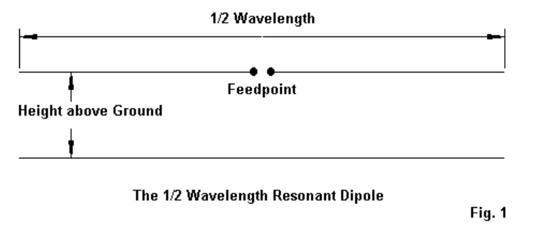
The 1/2-Wavelength Center-Fed Resonant Dipole The antenna that we loosely call the dipole is actually a 1/2-wavelength center-fed resonant or nearly resonant dipole. We usually construct it fromAWG #14 or #12 copper or copperweld wire for the lower HF bands, and we may use bare or insulated wire. Often, we mislabel multi-band doublets as dipoles because the antenna is about 1/2-wavelength at the lowest frequency of operation. But to be strictly correct, that antenna is a dipole only at the lowest frequency of use.

Fig.1 shows the two essential dimensions of a real dipole. Since we tend to feed the dipole with coaxial cable, we are concerned with the antenna length and resonance. In other words, we want a good match between the coax and the antenna feedpoint However, we also need to be equally if not more concerned with the antenna’s height above ground. The old adage, “The higher, the better,” arose from the use of wire antennas on the lower HF bands, where we generally could not achieve even a height of 1 wavelength.

Table 1.

Approximate Lengths of a Wave in Feet

Band     Frequency      Length                    Band        Frequency        Length
meters       MHz             feet                      meters         MHz                feet
160            1.8               546                         20             14.0                  70
80              3.6               273                         17              18.1                 54
75              3.9               252                         15              21.0                 47
60              5.37             183                         12              24.95               39.5
40              7.0               140.5                      10              28.2                 35
30              10.1              97.5
Table 1 serves as a reminder of how long a wavelength is on each of the HF amateur bands. For most backyard antennas, the average ham is lucky to achieve an antenna height of 1 wavelength on 10 meters, while the truly fortunate operator may get his wire to 1 wavelength on 17 or 20 meters. Every horizontal antenna is subject to essentially the same general phenomena that affect horizontal dipoles in terms of their height above ground. The lower the antenna as a fraction of a wavelength, the lower will be the overall gain and the higher the elevation angle of the radiation. Fig.2 illustrates the principle for a dipole placed at 1/4, 3/8, 1/2, and 1 wavelength above average ground. Unlike vertical monopoles, horizontal wires do not change their gain or elevation angle significantly with
changes in soil quality.
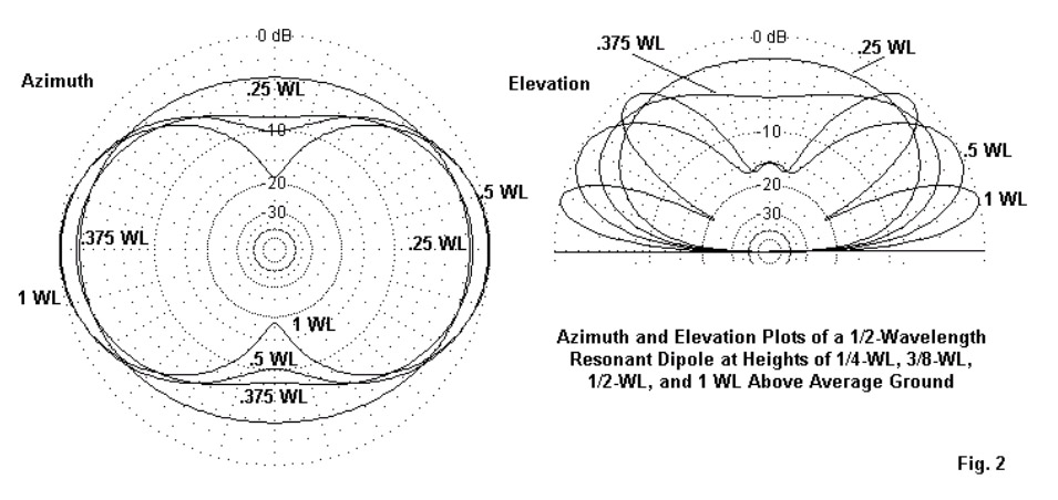
The elevation plots on the right show that the lower we place a dipole, the higher the angle of radiation, a fact that limits our effective range of communications under normal propagation conditions. The azimuth patterns on the left not only show the reduction of gain with a reduction in height, but as well the change in pattern shape. As we reduce the height of a dipole, its figure-8 shape at 1-wavelength devolves into a simple oval at a height of 1/4-wavelength. What applies to the dipole will generally but not without some exceptions, apply to any horizontal wire antenna relative to its height above ground at the frequency of operation. When it comes to height, think wavelengths, not feet! 1/2-wavelength resonant center-fed dipoles have many other interesting characteristics, but the ones that we have noted will guide us while we explore the top 5 multi-band backyard wire antennas. We shall also be setting aside our coaxial cable in favour of parallel feedline to an antenna tuner (ATU) or, as some British writers prefer, an antenna system tuning unit (ASTU). Consider the ATU to be a lifetime investment.

1. The Broadside Doublet(s): The broadside doublet is a simple multi-band doublet with a 4:1 frequency range for the desired characteristic. Fig. 3 shows the general outline.
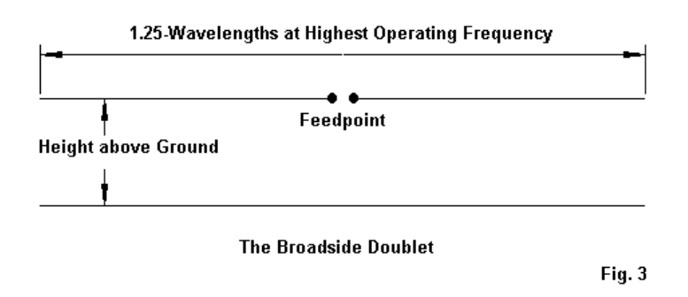
In principle, the doublet is physically no different from a dipole. However, electrically, it is
significantly different. First, we feed it with parallel transmission line to an antenna tuner, because the feed point impedance varies greatly as we change operating frequencies from one band to the next. Second, we select the length so that the antenna will show a bi-directional pattern broadside to the wire on all of the bands included. Note that the length makes the antenna an extended double Zepp at the highest frequency. With an antenna tuner, the antenna will operate above its highest included frequency, but the pattern will breakup into multiple lobes. Table 2 provides the most convenient lengths and the bands included.

Table 2. Broadside Doublet Lengths and Amateur Band Coverage
Length (feet)         Bands covered
44′               10, 12, 15, 17, 20, 30, 40 meters
66′               15, 17, 20, 30, 40, 60 meters
88′                20, 30, 40, 60, 80 meters
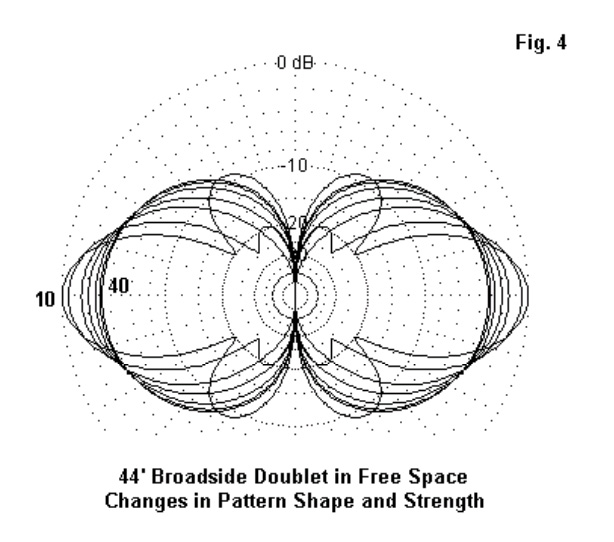
The chief advantage of the broadside doublet is that you always know the directions of your radiation or your most sensitive reception. A second advantage is the antenna’s simplicity for a 4:1 frequency range with the bi-directional characteristic. A third advantage, which we shall note shortly, is the flexibility of the antenna in forming wire arrays having different characteristics. With every set of advantages come one or more disadvantages. First, the antenna requires a wide-range ATU, since the impedance varies greatly from band to band.Since the exact values that will appear at the tuner terminals will vary with both the antenna height and the length and characteristic impedance of the parallel transmission line, I shall not provide specific numbers. Second, the gain goes down with frequency. The broadside doublet has its highest gain at the highest frequency. The gain drops a bit with each move to a lower band, while the pattern broadens. Fig. 4 shows the patterns overlapped in free-space models. However, remember that as we go down in frequency, the antenna will have a height that is a smaller fraction o fa wavelength. Hence–like the dipole–we can expect a further reduction in gain and a more significant increase in the elevation angle of maximum radiation. Hence,the higher you can place the antenna, he better will be its performance.
Part of the flexibility of the broadside doublet stems from the ease of covering the full horizon by adding only one more support. See Fig. 5.
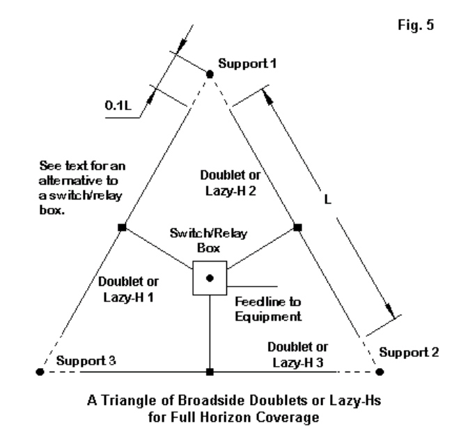
We can easily form a triangle of doublets. The triangle need not be perfect, so you can adjust it to aim more exactly at your favourite communications targets. With only a bit of end space(about 10% of the wire length), the inert wires will not materially affect the operation of the one in use. The only caution that you need to observe is to keep the feedline lengths identical. This caution applies whether you use a fancy switching box at the center of the array or whether you bring three separate and well-spaced lines to the shack entry point and do your switching indoors. Equal line lengths will mean that you do not have to do major retuning when switching from one antenna to the other. Hence, you can easily determine the most effective antenna for an incoming signal just by switching through the 3 antennas. Note that the triangle refers to either doublets or lazy-H antennas. That is part of the flexibility of the broadside doublet system. We can make lazy-H arrays using any of the listed element lengths and cover the same set of bands–but with more gain. Fig. 6 the outlines of a lazy-H.
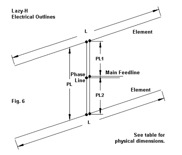
The lazy-H is simply 2 broadside doublets fed in phase. We need the center main feed point to ensure that the lines to both wires are the same length and therefore give us the same current magnitude and phase angle at both element feed points. So PL1 and PL2 are 1/2 of PL. The total length of the phase line assembly can be longer than the spacing, but for most installations, they are the same. The ideal spacing is 1/2 of L, the element length. Hence, the spacing is 5/8-wavelength at the frequency where the element is 1.25 wavelengths. This spacing provides maximum gain. You can reduce the spacing somewhat,but every reduction reduces the gain on all bands. The ideal lazy-H will net you almost 3-dB gain on the highest bands. There will be a slight reduction for the lowest bands, since the spacing will no longer be optimal. As well, the lower wire gets closer to the ground as a fraction ofa wavelength when we reduce the frequency.
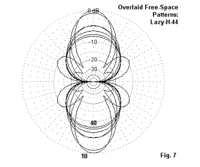
Fig.7 shows the overlaid free-space patterns to give you a basic idea of what happens to shape and strength,but remember to modify your expectations depending upon the height that you place the antenna. Getting the lowest wire at least 1/2-wavelength above ground is best,although lower heights for that wire will work. However, if that wire will be under 1/4-wavelength above ground, you maybe better off with a simple broadside doublet at the upper level. It will give you a lower radiation angle than the pair of wires. As a side note, in any set of in-phase fed antennas–whether doublets, Yagis, or whatever–the effective height of the combination will be a point about 2/3 the distance between the lowest and the highest antennas. Of course, we can make a triangle of lazy-Hs, just as we can for the basic doublet. There is a second multi-band array that we can make from the broadside doublet: an 8JK.
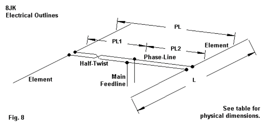
See Fig. 8 for the outline. Developed by John Kraus, W8JK, in the1930s, the antenna has undergone many variations. The versions shown here is designed for a 3:1 frequency range. It uses the broadside doublet lengths for the highest frequency,along with a total phase-line length that is 1/2 of the element length, L. However, note that when we create this end-fire array, we give one (and only one) of the phase line sections a half twist. The specific dimensions we have chosen from W8JK’s work are ones that give us an interesting pattern of gain, as shown in the free-space patterns of Fig. 9. The free-space gains are about equal on all bands. Indeed, the only factor that limits our frequency coverage is a very low impedance below the listed frequency limit.
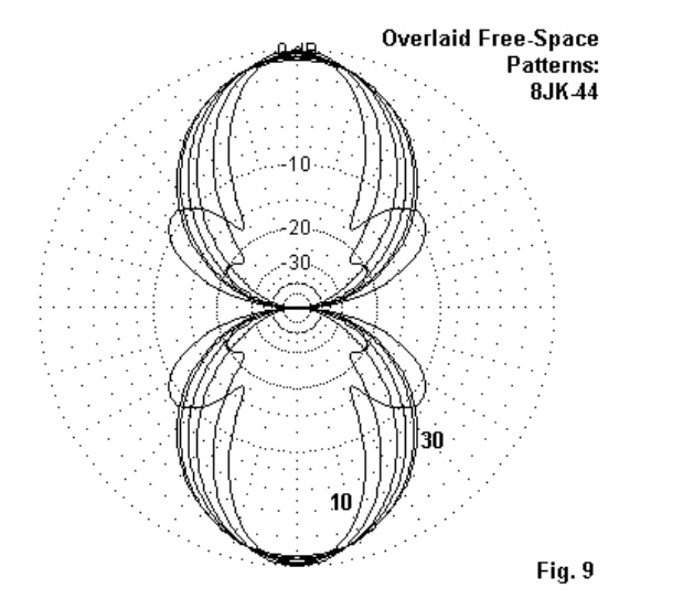
Of course, over ground, the gain will decrease as we lower the frequency,since the array will be lower as a fraction of a wavelength. Within the included bands, the gain will be much more equal from band to band than with the lazy-H. However, the peak gain will not be as high at the highest covered bands.

We may summarize the array dimensions in a simple table(Table 3). Remember that since we are using parallel feedline and an antenna tuner, broadside doublet lengths are not finicky. However, in the arrays, strive for equal lengths for each element.

Table 3. Lazy-H and 8JK Dimensions
Element Length       Phase-Line            Bands covered (meters)
(L, feet)            Length (PL, feet)             Lazy-H                8JK
44′                          22′                          10 – 40              10 – 30
66′                          33′                          15 – 60              15 – 40
88′                          44′                           20 – 80             20 – 60

2. The Dipole-Doublet(s): The dipole-doublets differ from the broadside doublets in two respects. First, rather than determining their length based on the highest frequency of use, we determine it based on the lowest frequency.In most cases, the doublet is a 1/2-wavelength dipole (approximately) at the lowest frequency. (Even the G5RV doublet is a dipole on 60 meters.) Again,since we shall use parallel feed line and an ATU, we do not have to be finicky in setting the exact length. Second, we do not give any preliminary thought to the lobe structure of the radiation pattern when we set up a dipole-doublet. Usually, we know that thepattern is bi-directional at the lowest frequency. However, we often do not think about the pattern above that frequency. As we shall see, the bi-directional patterns holds true until the antenna length as measured in wavelengths is greater than about 1.25.However, for many users, the patterns for the higher bands are mysterious. To get us started, Fig. 10 outlines the basic dipole-doublet. It chief advantages are simplicity and the ability to cover all of the HF bands above the frequency for which the wire is a 1/2-wavelength dipole. Hence, the preferred lengths are usually about 260′ for 160-meter coverage, 135′ for 80-meter coverage, and 67′ for coverage down to 40 meters. As noted, the G5RV 102′ doublet manages to be a dipole at 60 meters. The 67′ length will load on 60 meters, and the G5RV will load on 80 meters. In each case, the wire is about 1/3-wavelength,close to the limit for a center-fed wire.Below that length, the resistive part of the impedance goes too low and the capacitive reactance goes too high for most parallel line and tuner combinations to handle.
To start the process of becoming familiar with the typical patterns of a dipole doublet, examine Fig. 11. The dipole-doublet’s length in feet matters less than how long the doublet is at a given operating frequency in terms of half-wavelengths. When the length is close to an even number of half-wavelengths, we have as many lobes as we do half-wavelengths. The strongest lobe moves farther from a broadside direction as we increase frequency. As well, the beam width of the strongest lobe becomes narrower. Because the ham-band operating frequencies do not result in exact multiples of a half-wavelength, the lobe strengths will vary. But the count remains true.

If we operate the same antenna at odd multiples ofa half-wavelength, we obtain patterns composed of both emerging lobes and diminishing lobes. So the number of lobes is the sum of the old even number of half-wavelengths and the new even number of half wavelengths. In other words, we have twice the number of lobes as we do the length in half wavelengths. See Fig. 12. Again, because the nearest ham-band frequencies are not precisely the number of half-wavelengths listed, we find some of the lobes weaker than others. However, the count remains true.

The patterns would change if we used a 102’or a 67′ doublet when referenced to specific frequencies. However, relative to the frequency at which the doublet is 1/2-wavelength long, the patterns would re-emerge as shown as the antenna approaches lengths of 1 wavelength, 3/2 wavelengths, 2 wavelengths etc. In addition, the dipole-doublet is subject to the same rules relating antenna height as a fraction of a wavelength to radiation elevation angles that we discovered for the resonant dipole. If we understand the pattern development of a dipole-doublet, we can successfully use it without disappointments. The feed point impedance will vary over a wide range. In fact, it will be very high whenever the doublet is a multiple of a full wavelength. Hence, many users prefer 600-800-Ohm ladder line so that the line is an intermediate impedance between the highest and lowest values encountered. I like the old dipole-doublets for their simplicity and their long tradition of successful use. They are also flexible. We can set up a triangle of them, but the complex patterns may not give us the full horizon coverage of the triangle of broadside doublets. There is even an old (1930s) trick that we can use with the dipole-doublet: the center-support Y. Fig.13 shows the general outlines. The sketch shows 67′ legs, comparable to a 135′ doublet.However, you can use 50′ or 35′ legs with reduced low band coverage.
The Y-doublet’s special feature is the use ofa non-conductive center support (which may be no support at all if you can devise a way to hang the center freely). Either by spacing wires from a center pole or using triangular spacers, we bring down 3 wires, one from the inner end of each leg. The down-wires form the parallel transmission line. At the shack entry point, we set up a switching system to select the pair of wires to form the transmission line for the active doublet. In most cases, it will not matter whether thethird wire simply floats or is grounded:it is centred between the 2 active wires and has
almost no current on it. The Y-doublets form 120-degree angles. This angle makes almost no difference in the pattern relative to a linear doublet. There will be some differences in the patterns on the upper bands compared to those we saw for the linear doublet. Nevertheless, you will use an A-B-C switch to determine which pair of legs provides strongest signal. In order to make radical re-tuning unnecessary,itis important to
keep the transmission line wires equally spaced in a triangle all the way to the switch at the shack entry point. The Y-doublet is one way to overcome some of the limitations of the dipole- doublet’s multiple lobes on the upper HF bands.

3. Fanned Dipoles: For coax lovers, mythird selection for a multi-band antenna is fanned dipoles. I have seen a myriad of designs for these antennas, some of which include up to five or 6 bands and fold the longest elements into spaghetti. These designs I do not prefer, because they have very narrow operating bandwidths and erratic patterns due to combining long and short elements that both offer low feedpoint impedances. For reliable service with decent bandwidths, I prefer to construct my fanned dipoles a couple of bands at a time so that when one band shows a low impedance, the impedance of the other band is high. As well I prefer to widely space the shorter element outer ends from the longer element and obtain a wider operating bandwidth on both bands. In short, my preference in fanned dipoles is a 2-band antenna,although I would not rule out a 3-band combination. Fig. 14 shows the general outlines with the critical dimensions noted. Ordinarily, we support the outer ends of the longer dipole and suspend the shorter dipole beneath.

Let’s get a handle on the properties of fanned dipoles with a simple 80-40-meter combination. We shall look at two versions of the same antenna. One will droop the 40-meter dipole 10′ below the 80-meter dipole. The other design will place the 40-meter outer ends 1′ below the low-band dipole. The 80-meter dipole is set for 3.6 MHz, while the 40-meter dipole is set for 7.1 MHz. Table 4 gives us the dimensions and the performance of the array on each band with the 80-meter dipole 50′ above average ground.

Table 4.

Fanned 80-40-Meter Dipole Dimensions and Modelled Performance at 50′
Frequency     Length          Gain                   TO Angle                 Feedpoint Z
MHz                 feet             dBi                     degrees                  R+/-jX Ohms
Wide-Spaced Version
3.6                130.4            6.63                     86                              61 – j 1
7.1                  67.0            4.82                     44                              54 – j 0
Close-Spaced Version
3.6                 130.4            6.80                     88                               61 + j 2
7.1                   75.3            4.85                     40                               58 + j 2
Although there is no significant difference in performance at the two design frequencies between . the wide and the close dipoles, we certainly can see a difference in the length of the 40-meter dipole. The wide-spaced version shows a length that approximates the length of an independent 40-meter dipole. However, the close-spaced version requires a much longer 40-meter element. Remember that the close spacing is still 1′, which is wider than some published and commercial designs.
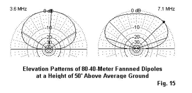
Fig. 15 shows the elevation patterns for the two bands. Like all horizontal antennas at low heights, neither pattern is ideal. The antenna on 80 meters is below 0.2 wavelength, and it only achieves 0.36 wavelength on 40 meters. As with all of the horizontal wire antennas, it could benefit from additional height.

We cannot see much difference in performance between the two versions of the antenna on the design frequencies, but we did note the 40-meter dimension change to obtain that performance. The 80-meter length did not change as we altered the spacing of the 40-meter ends from the 80-meter wire. Obviously, in a fanned dipole arrangement, we expect the shorter wire to undergo more change than the longer one. The question is how we can sample the long-wire stability and the short-wire variability.

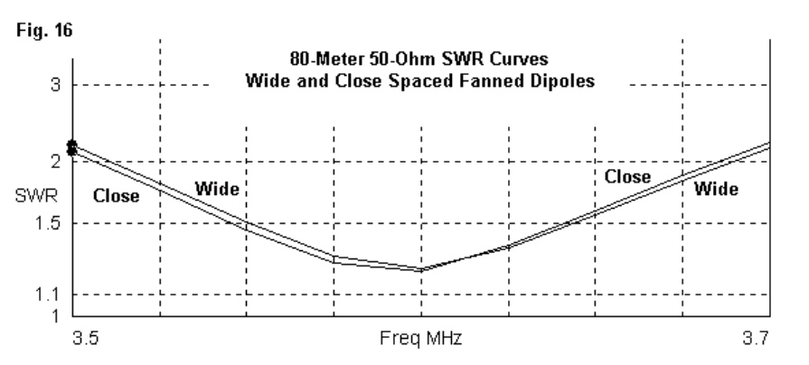
One way to see the difference is to examine the 50-Ohm SWR curves for the two versions of fanned dipoles. Since the 80-meter wire remained stable, we would expect the SWR (as a measure of changes in resistance and reactance also to remain stable. Fig. 16 tells the story.
The 40-meter 50-Ohm curves stands in stark contrast, as revealed by Fig. 17. The wide-spaced version of the antenna covers over 2/3 of the band. The close-spaced version barely handles 100 kHz. While the narrower bandwidth may be satisfactory for some operational needs, it also indicates that pruning the close-spaced 40-meter dipole to length is likely to be a somewhat ticklish task.
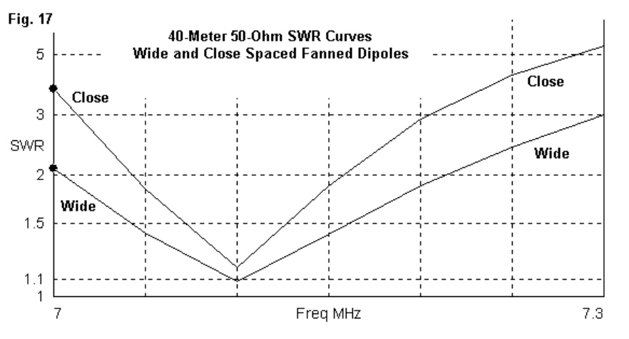
To understand why closing the space between the dipoles shrinks the usable passband of the higher-frequency dipole, we should make at least one more probe into the operation of the antennas. Modelling software gives us a look at the current distribution along the dipoles. Let’s compare the currents on both versions of the array.

Fig. 18 shows in the curves on the left the relative currents on the wires during 40-meter
operation. Notice that, despite the high impedance of the 80-meter dipole, there remains a low but significant current on the wire. Even with wide spacing and a predominance of current on the 40-meter wire, the two dipoles do not achieve the kind of independence that casual fanned-dipole theory suggests. When we move to the right and examine the closed spaced version ofthe array, we see a considerable increase of current on the 80-meter dipole. The closer that we space the two dipoles,the higher the current on the longer one. The higher the current that we find on the longer dipole, the narrower will be the operating passband of the shorter dipole and the more painful will be the job of setting its proper
length. As well, we are likely to find that a set of lengths that is right for one antenna height is not right for a different height. Fanned dipoles have served me well over the years, but only when I restricted the number of bands covered and when I separated the shorter dipole ends as far as feasible from the longer wire. As well, a 2:1 frequency ratio has tended to yield the most successful antennas with the widest operating bandwidth. Still, do not count the fanned dipole out when it comes to flexibility. I once tied a 10-meter vertical dipole to a horizontal 15-meter dipole with good success. One might even use close spacing (and patient pruning) to set up a combination for 12 and 17 meters or for 17 and 30 meters, where operating bandwidth is less of a question. However, I likely would steer away from combinations like 40 and 15 meters or 30 and 12 meters.

4. The HOHPL–Horizontally Oriented and Polarized Loop: The horizontal loop is subject to several misconceptions. Two of the most popular are that 1. The longer I make the loop, the more gain I get, and 2. The loop gives me omni-directional coverage on all of the HF bands. Basically, if you want more gain, then place the antenna higher. Moreover, even if you create a perfect circle, your pattern will not be circular on almost any band. Nevertheless, the loop is a good multi-band antenna easily fed with parallel transmission line and an ATU.
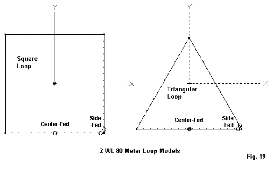
Fig. 19 shows the outlines of the two most popular shapes for a horizontal loop: the square and the triangle.Almost any other closed shape–regular or irregular–is possible. Most polygons with more sides tend to act like squares, so the contrast between the square and the triangle become good guides on what to expect from a loop strung along the perimeter trees in an average yard.Each loop shows 2 (different) feedpoints: a mid-side location and a corner location. These two points tend to coincide with the most convenient installation points from whichto runthe parallel feedline fromthe antenna to the
ATU. You can select an alternative position and nothing evil will happen. However, the patterns will not be as regular as the ones that we shall use for demonstration purposes.
I prefer to use a 2-wavelength loop at the lowest frequency ofoperation. In fact, our
demonstration loops will be 560′ loops with 80 meters as the lowest band. Loops have a peculiarity.

If we make them about 0.75-wavelength or smaller, they tend to radiate off the loop edge. If we make them close to 2 wavelengths or larger, they also tend to radiate off the edge. However,if we make the loop 1-wavelength–or thereabouts–at the frequency of operation, then it radiates broadside to the loop. Hence, a horizontal 1-wavelength loop becomes a good NVIS antenna, as our 80-meter 2-wavelength loop would become on 160 meters. Incidentally, we shall place the demonstration loop 70’above ground simply for the exercise.70′ is about 1/4-wavelength on 80 meters but 2 wavelengths on 10 meters. The phenomena of changing planes of radiation as we enlarge a loop will explain why my list of
the top five multi-band antennas does not include any vertically oriented loops. Lets start with a 1-wavelength loop.It does fine on the band for which it is cut. However, by the time we double the frequency of operation,the loop is radiating off the edge, producing mostly high-angle radiation. Such loops will make contacts, but not as well as a horizontal loop.
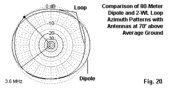
On the lowest band of operations, we do not choose the loop for gain. As shown in Fig. 20, there is very little gain difference between the loop and a resonant dipole at the same height. The mid-side-fed square loop used to generate the loop part of the pattern is not even significantly more omni-directional than the dipole pattern. However, at their lowest operating frequencies, loops tend to show a lower radiation angle than a low dipole. In the case that uses antennas at the 70′ level, the dipole’s take-off angle is 58 degrees, but the loop’s angle is between 44 and 50 degrees, depending upon the loop shape and the feed point position. This advantage is useful at the lowest operating frequency, but it does not last as we increase frequency. By the time we double the operating frequency,the take-off angle for loops tracks well with the take-off angles for doublets at the same height.
Loop antenna shape and the position of the feedpoint do make a difference to the antenna’s pattern and performance.

Fig. 21 shows the 3.6-MHz azimuth patterns for the two loops (square and triangular) with both corner and mid-side feed points. The notation FP on the plots shows the relative position of the feed point to the development of the plot. The triangular plots are–relative to the feed point position–more alike than the two plots for the square loop. In both triangle cases, the direction of the main lobe crosses the feed point and a point in the middle of the opposite side. The main difference is a reverse in the slight gain advantage. For the corner-fed triangle, maximum gain is away from the feed point, while in the mid-side version, gain is more toward the feed point. The squares, however, show a more distinct pattern difference, depending upon the feedpoint position. The corner feedpoint produces a nearly circular pattern, while the mid-side feedpoint yields a 4-lobe pattern. Although there are no major differences in gain, Table 5 presents the modelled maximum gain values and take-off angles for the 4 loops on various HF bands, using our basic 560’loops at 70′ above average ground. Because we shall use an ATU, the feedpoint impedance data is not especially useful here.
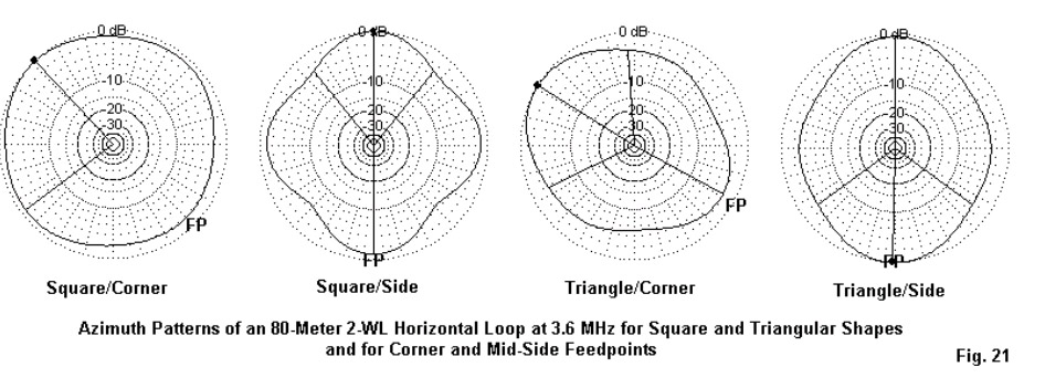
Table 5. Modelled Performance of 560′ Horizontal Loops at 70′ on Selected Amateur Bands

Note: Performance shown as Maximum Gain (dBi)/TO Angle (degrees).
Loop           Square             Square             Triangle              Triangle
Frequency   Corner-Fed        Side-Fed         Corner-Fed         Side-Fed
3.6              5.9/50               6.7/44                7.1/48              6.4/45
7.0             10.6/27              9.9/26                9.7/28             10.4/28
14.0            12.9/12            11.6/12              13.9/13             11.2/13
21.0           14.6/9              14.3/9                13.4/9               12.4/9
28.0            15.1/7              13.6/7                14.1/7                11.0/7
I have inserted Fig. 22 immediately following the chart of modelled gain values so that you will not make too hasty a decision on which loop to select. It shows the patterns on 40 through 10 meters that produce the gain figures in the chart, at least for the square loops. Above 40 meters, we discover patterns with many lobes. The higher we go in frequency,the more lobes we encounter and the more variable we find the lobe strength. As a general rule of thumb with simple wire antennas, the higher the gain of a lobe, the narrower its beam width. So we obtain maximum gain only over as mall target communications arc. In these patterns, dots serve to locate the feed point position on the loop relative to the pattern.

Fig. 23 provides the corresponding patterns for the triangular loop. On 80 through 20 meters, the loop produces patterns that have a distinct axis on the line formed by the feedpoint and the opposing loop position. Above 20 meters, the patterns become as individual as snowflakes, each very regular but distinct from the other patterns. When we combine the patterns of the three plot figures together, we may finally come to understand that on the upper HF bands, horizontal loops do not produce patterns that are more omni-directional than doublets. The patterns are simply different in the relative positions o the lobes and nulls. As well, the chart shows that on the upper HF bands, the radiation angles are similar to those of simple wire doublets.

So why choose a horizontal loop as one’s multi-bandwire antenna? One good reason is the improvement in radiation angle on the lowest frequencies of operation. A second good reason is because you have the perimeter supports already growing in your yard.A third reason is because closed loops tend to be less prone to the build up of static charge relative to doublets with un-terminated ends. This feature does not guarantee immunity from all noise sources. Nor does it guarantee immunity from the hazards or lightning and associated thunder storm dangers. A fourth reason is becauselarge closed loops tend tohave less high-angle radiation. What may be more important, this fact means less receiving sensitivity to high-angle sensitivity to QRM andQRN from closer-in sources. Fig. 24 compares the 21-MHz elevation patterns for a simple 135′ linear doublet and a 560′ triangular loop with its feedpoint in the middle of oneside. Although the exact shapes of the
15-meter elevation patterns will vary from one loop to another in the set that we have been examining, they all share the general property of having less high-angle radiation. The loop has several advantages that recommend it as a multi-band antenna,if you can live with the upper band patterns, if you have room for the array, if you can find the wire and the supports, and if you are prepared for the maintenance that a long stretch of wire requires. All those “ifs,” of course, represent the disadvantages of the horizontal loop.

5. The Inverted-L: In principle,the inverted-L is any antenna that physically looks like a tipped-over letter L. Electrically, it includes not only tuned systems with radials, but as well, any sloping wire that runs from an antenna tuner at ground level to some higher end-point. (A sloping wire has essentially the same vertical and horizontal radiation components as the more formally positioned L.) What we used to call a random length, end-fed wire belongs in this group as much as the 160-meter inverted-L with 64 radials at its base. In more practical terms, the average backyard antenna builder is unlikely to lay down a major radial field for the most efficient 160-meter operation. The portion of the antenna above ground is no problem, since it involves running a wire up as high as available supports will permit and then running the remainder horizontally. The radials are the major hindrance to using the inverted-L. So let’s reduce the radial field to a mere 4 radials, each 1/4-wavelength long at 160 meters, that is, about 135′. With this reduced field,let’s assume that we have 50′ of vertical support. Then an all-band inverted-L will look something like the left-hand portion of Fig. 25,
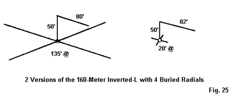
To achieve resonance on about 1.85 MHz with AWG #12 wire throughout, we need an 80′
horizontal run. Incidentally,in my model, the radials are buried 6″ deep in the ground, but the exact burial depth is not critical.Now let’s add a second dose of reality. Many hams have backyard filled with gardens, children’s toys, garages, etc. Hence, we find an unwillingness to commit to more than short radials. So the right-hand side of Fig. 25 shows the same set-up with 4 20′ radials. The horizontal section of the antenna needed a 2′ extension to restore resonance at 1.85 MHz.Now let’s compare performance (Table 6).

Table 6. Inverted-L Performance with Full and Short Radial Systems
Antenna 135′ Radials 20′ Radials
Frequency     Gain       TO Angle         Feed Z        Gain      TO Angle       Feed Z
MHz            dBi    degrees R+/-jX   Ohms          dBi         degrees     R+/-jX Ohms
1.85 -2.2         29                38               – j 2           – 2.6             29              47 + j 2
3.6 3.5           84            4500+ j1750 3.8 84 5200- j150
7.0 4.0 35 700 + j 750 4.0 35 900 + j 800
14.0 5.2 22 300 + j 300 5.3 23 350 + j 350
21.0 6.0 13 200 + j 80 5.8 13 250 + j 200
28.0 7.7 10 200 – j 100 7.5 10 200 + j 30

In practical terms, we find a significant performance difference only on 160 meters. The #12 inverted-L is under ideal conditions about 2 dB less effective than a full size vertical monopole. When we shorten the radials, we lose another half-dB of gain. Otherwise, the two systems are roughly equivalent for all-band operation. The short radials and longer horizontal section of the smaller system do raise the impedance values, but if a tuner will handle one set,it will also handle the other. Fig. 26 shows the patterns for 160 meters, with the antenna orientation marked. Note that the horizontal section offsets the vertical monopole pattern away fromitself bya small amount. Also note that there is still significant current in the horizontal portion ofthe antenna. This shows up as the figure-8 horizontallypolarized component of the pattern that is about 10-dB down from the vertically polarized component. As we move above 160 meters, we can discover one reason why many inverted-L users think of the antenna as a good (even if not perfect) general communications antenna. Fig. 27 provides patterns for selected hambands, with the frequency and the TO angle noted for each azimuth plot. Relative to patterns for closed loops and linear doublets, the patterns are almost all more equally distributed around the horizon. As we increase frequency, the combination of increasingly strong horizontally polarized radiation and the remnant vertically polarized radiation tend to provide a modicum of gain in almost every direction. Only when we reach 10 meters do we find a pattern of well-defined lobes and nulls, but the nulls are not as deep as those we find with loops and linear doublets. The cost of the fuller coverage is lower maximum gain. There is no significant difference between the pattern shapes for the L with a full radial field or the L with short radials. Remember that these patterns apply to an inverted-L with a 50′ vertical section. If you bend the L at a lower height, the TO angles for 80 through 10 meters will rise, and the gain and exact pattern shape may change. However, let’s consider one more version in which the user does not lay down a symmetrical (or thereabouts) radial field. The one thing necessary to the use of the inverted-L is a good RF ground, so this user lays down 1 buried radial about 20′ long. See Fig. 28.
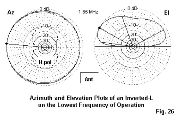
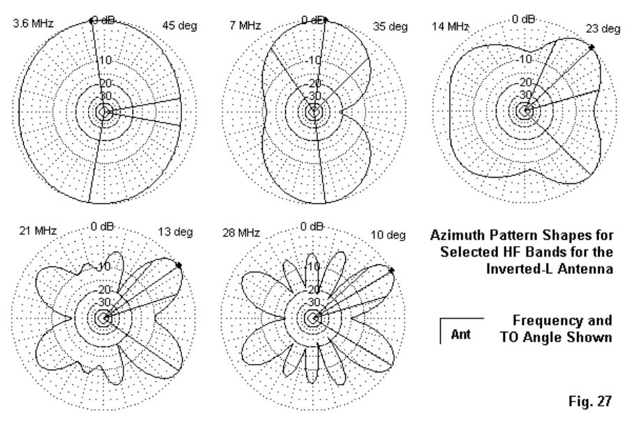
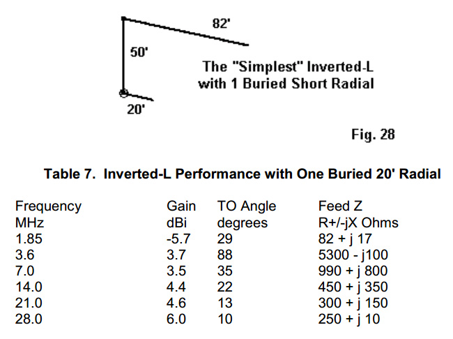
Table 7. Inverted-L Performance with One Buried 20′ Radial
Frequency Gain TO Angle Feed Z
MHz dBi degrees R+/-jX Ohms
1.85 -5.7 29 82 + j 17
3.6 3.7 88 5300- j100
7.0 3.5 35 990 + j 800
14.0 4.4 22 450 + j 350
21.0 4.6 13 300 + j 150
28.0 6.0 10 250 + j 10

As Table 7 shows, performance does diminish relative to the other systems. However, only on 160 meters, where we lose another 3 dB of gain, is the result unworkable. On the other bands, we obtain usable performance. For emergency and field operations, the 1-radial inverted-L may be usable from 80 through 10 meters. However, for home use, we should strive to add as many radials shaped however the ground will permit–as we can, even if weonly add one every few months. The usual safety precautions apply to radials: get thembelow ground where playing children, gardening spouses, and seeing-eyelawn mowers cannot reach them. If you usea tree to support the feed-end of the antenna, be
sure to space the vertical well away from the tree trunk. In addition, make sure that no one can touch the antenna or its feedpoint during operation.

You will note that the 80-meter impedance is very high, higher than most antenna tuners can handle.For this reason, many inverted-L users prefer to use wire lengths longer or shorter than the 130′ length that I used in this demonstration. A 3/8-wavelength inverted-L (about 100′ including both the vertical and horizontal sections) will move the very high impedance frequency to the 30-meter band. Pattern shapes will change, but the general properties of the inverted-L will remain: good (but not great) bulbous patterns for general communications in almost every direction. One final question: where do I place the antenna tuner? The answer is simple: at the antenna feedpoint. This position is standard in the field, where we usually terminate the antenna at the operating position with a manual antenna tuner. For this antenna, we actually need a single-ended network tuner. At home, the inverted-L is an ideal application for one of the weather protected automatic tuners (using precautionary additional weather shielding) with the case or ground lead connected to the radial side of the system.

The advantages of this type of system are obvious: automatic (or semi-automatic) tune-up with a coaxial cable from the antenna feedpoint to the rig. The disadvantages are the initial expense of the automatic tuner and periodic preventive maintenance. Final Notes: We have now surveyed my personal five favourite multi-band wire backyard antennas. There are others that I might have included. In fact, I thought of some others, but gradually discovered that they were mostly variations of the ones that I included. For example, there are some sloping and bent wire antennas calling for either measured or random-length “counterpoises.” However, they are simple variations on the inverted-L. Linear dipole-doublets have inverted-Vee variations. I have omitted antennas using traps, simply because traps require maintenance and represent an advanced project for most folks who roll their own.

All of the antennas I chose involve only wire and feedline plus, of course, the antenna tuner. For all but the inverted-L (and possible the fanned dipoles), we need a balanced tuner that will handle a very wide range of resistance and reactance at its terminals with the highest possible efficiency. Although there are a few balanced network and Z-match tuners available, most hams still use single-ended network tuners with a 4:1 balun at the terminals. Unfortunately, not all 4:1 tuner baluns are made equal, and many show high losses in the presence of either high reactance values or very low impedances that may occur as the feedpoint impedance is transformed along the parallel feedline. There is an alternative system for using the single-ended network tuner in the manner in which it is most efficient: as a single-ended network. Fig. 29 shows the essentials.
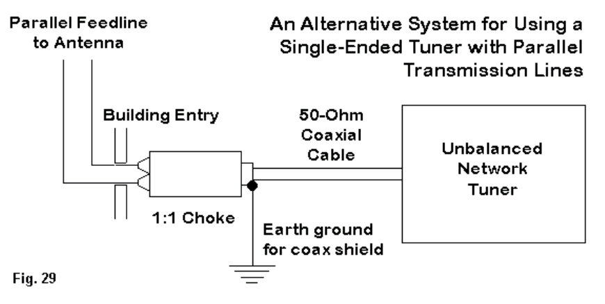
At the shack entry point, we terminate the parallel feedline with a 1:1 balun.Actually,the unit is a simple choke in preference to a transmission-line transformer that prefers a minimum of reactance. A W2DU type choke composed of about 50 ferrite beads around a length of coax tends to work quite well in this application. We run a lead to an earth ground from the coax braid right at the coax side of the choke itself. This measure tends to attenuate any remnant RF that might get onto equipment cases or into circuitry. Make the coax run as short as possible using the lowest-loss coax that you can obtain, since there will still be a considerable SWR on the line to the tuner. However, this line goes directly to the coax connector on the tuner output side for single-ended processing. The system is not perfect and does have small losses. However, in most cases, it tends to clear the shack of unwanted stray RF from indoor parallel feedlines, and it does allow the single-ended tuner to effect a reasonably efficient match with the remainder of the antenna system. This system is not new,being almost as old as the W2DU type choke itself. I first recommended it as one solution to problems some folks had back in 1980 with G5RV antenna systems.
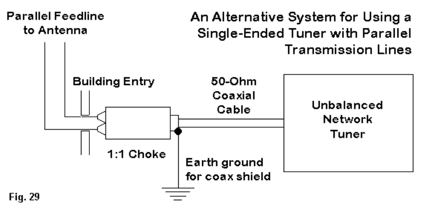
There is a vast territory that these notes have not covered. We can make multi-band beams, multi-band verticals, and a number of other antennas that will cover 2 or more of the ham bands. I encourage you to experiment with antennas, since wire is inexpensive and you can develop temporary mounts to put up and take down your trial antennas. But when you do erect an antenna, please be sure to give it that same care that you give your transceivers. Periodic preventive inspection and maintenance will ensure that the antenna gives you all the performance that it can every time you fire up the rig. Attention to safety will protect both property and the lives of those you love the most including  yourself.
As for those other possible antennas, there are always future FDIM celebrations to cover them.

73 L Cebik W4RNL
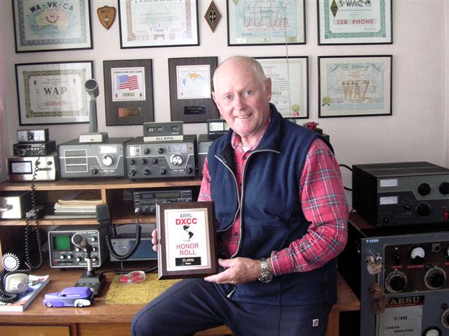
Troubleshooting Antenna Traps

TROUBLESHOOTING TRAPS

Below is a document that was produced by staff members at Cushcraft some years ago.. I have reproduced it here but it remains of course, copyright of Cushcraft Corporation… 

It refers mainly to the old 1/4 wavelength AV series of antennas (12AVQ, 14AVQ etc) hence the references to radials..  The “R” series (R5, R7 etc) are 1/2 wavelength antennas, and the radials are NOT 1/4 wavelength resonant..

If you fail to get a good VSWR on one band there are three possible problems. The first is that the trap is bad or mistuned. Another is that the radials are incorrectly measured or attached. The third is that the length of the radiator has changed, possibly becoming shorter because of a loose clamp allowing one section of tubing to slide into another section.  Check physical dimensions and connections first. Always troubleshoot a trap antenna problem working from the highest frequency to the lowest.. One way to test the radials is to attach temporarily one more quarter wavelength radial that is carefully cut to the correct length for the band on which the problem occurs.  Did the VSWR decrease? If so, then improve the radial system, if it did not, then there may be a trap problem.

A trap is a high Q parallel resonant circuit. If the antenna works on the next lower band, then the coil of the trap is good, and has good connections to the aluminium tubing. If the next lower frequency does not work then the coil may be open. The balance between inductance and capacitance Is critical, and requires good equipment to assure proper adjustment. Refer to the trap trouble-shooting section for checking individual traps.

SWR CHANGES WITH THE WEATHER

Ice or heavy sticky snow that sticks to the radiator and traps will cause the resonant frequency to shift lower, due to a fatter radiator. If your antenna is ground mounted and you have only a few radials then in wet weather ground conductivity may change and therefore VSWR will change as soil conductivity varies. Any cracked, torn or wrong size plastic caps on the top of traps will allow moisture in, affecting the resonant frequency. Putting any type of sealant on the top of the traps will likely detune them and create voltage breakdown problems since the top of the trap is a high voltage point.

VSWR CHANGES WITH POWER

If VSWR varies with power level on one or more band the problem may be in the VSWR bridge. There can be a non linear variation of diode action at different power settings. This is common with inexpensive bridges. It is possible to overload a diode in the forward power mode. The diode is now on a different slope of the curve in relation to the reflected power diode which is not overloaded. The end result is that your VSWR will apparently increase when you go from low to high power. Example: 1.1:1 at 50 watts , 1.4:1 at 800 watts. Observe VSWR as you slowly increase power. If VSWR slowly increases you may be over­loading your bridge. If you see a large jump in VSWR at a specific power level not related to a slow increase in power, you could have voltage breakdown troubles with your antenna

Causes: Poor, or Intermittent connection in the radial system. Poor connection in a trap. High voltage breakdown on a trap, (sniff the end cap to see if burned). High voltage breakdown in Input coaxial connector or matching network (if supplied).

VSWR too high on one or more bands.

Causes: Mistake in assembly. Poor, or no ground or radial system. Defective trap, See trap troubleshooting.

TRAP TROUBLESHOOTING 

On the AP-8 antenna check the connections at each trap.. Is the ground screw tight? Are the screws tight at each  strap  connecting  the  radiator  tubing  to  the capacitor tubing?  A poor connection at any  of these points will cause that trap to be detuned and result in poor VSWR on the band for which that trap was tuned. If you  have the AV-5 antenna check each  trap to insure that the cover is tightly secured.   The cover is the 1 5/8″ aluminium tubing over the coil, On top of the cover is a plastic cap. Any movement of the cover will cause intermittent VSWR conditions on the antenna. You   may  test for  a  loose  cover  easily   while   the antenna Is still assembled. Grasp each trap in your hand and apply a moderate amount of pressure in a clockwise and then  in  a counter clockwise  direction about the axis of the element. If the cover slips It will require tightening. A hex head screw Is at the base of the trap. Tighten this screw with an appropriate screw driver or spintite.  Be careful not to apply  so much force as to strip out the sheet metal screw. If the hole is already stripped, or gets stripped accidently, it is an easy matter to fix by substituting a #10 x 3/8″ or #10 x 1/2″ self tapping screw in the enlarged hole, If all your traps pass the mechanical test, and seem to be installed properly, then a frequency check is in order. The traps should be marked before removal so that proper re-assembly is assured. Remove all of the traps and bring them Indoors for inspection.   A list of Cushcraft traps and resonant frequencies are presented below, so that you can check to see if a trap is near the frequency to which it should be tuned. Use as little coupling as possible so that the dip oscillator Is not pulled in frequency. Use a frequency counter or receiver to determine the frequency of the dip oscillator. (Nowadays we can use our Antenna Analysers of course are sexier than a GDO..)

TRAP     OPER FREQ        OSC FREQ               OSC COUPLING

TF                   28.8                    27.87                            Capacitive

TG                   21.3                    20.17                             Capacitive

TH                   14.2                     12.92                            Capacitive

TJ                    7.20                      5.81                              Capacitive

TR                   21.3                    20.23                             Capacitive

TQ                   28.7                    26.8                                Inductive

24.65                 23.5                                Inductive

TS                   21.25                  20.1                                Inductive

18.11                  17.5                                Inductive

TT                    14.47                  13.49                              Inductive

TU                   10.19                    9.9                                  Inductive

TV                   7.3                        5.8                                   Capacitive

The method of coupling to the dip oscillator is important. Traps from the AV series of antennas require capacity coupling because the coil is shielded. Place a trap on an insulated surface (large cardboard box) and couple your dip oscillator meter (GDO) to the trap as shown below. Be careful to follow directions explicitly.

Capacitive Coupling

For capacitive coupling the tip of the GDO coll should be just slightly Inserted into the lower end of the aluminum tubing of the trap. Inductive coupling can be used where the coil is visable except for the TV  trap  where  the  dip  can  be  found   easier  by capacity  coupling. When checking dual  frequency traps   (TQ  & TS)  short the trap  not  under test to prevent obtaining a false reading. It should be noted that  the  dip   meter frequency   is   lower  than   the operational   frequency   of  a  trap.   This   is   caused because the trap will load the dip oscillator and lower it’s  frequency.  You should  use the listed  oscillator frequencies as a guide.   Temperature and   humidity can have a   +/-   100  KHz  effect  on   traps.   If the readings are within 100 KHz of the listed amounts, do not worry, the effect upon the assembled antenna will be minimal, Shorted turns or other serious defects will cause wide   shifts from the norm. One or two megahertz is a definite indication of a bad trap . All coils are sealed and are difficult to repair properly. When all traps are checked and corrected,  reinstall them   in   proper  order,   (as  you   previously   marked them)  and your multiband trapped vertical is now ready for action.

Inductive Coupling

Below is part of an email that I received from Dick W5TA which contains more “hands on” experience of fixing traps..

Getting ready for Field Day, I repaired an old  HyGain tribander which belonged to our local radio club. We found that the connections of the copper wires in the trap coils to the screws connecting them to the aluminium tubing had seriously corroded. With most traps there is one or more retaining screws.  After their removal you can pull off the end caps and pull the trap apart.  It’s an outer aluminium tube over a plastic inner rod serving as a coil form.  Often you will find bug nests, insect carcasses and corrosion bridging turns of the coil as well as corrosion at the terminals and maybe the whole coil.  If you rewind the coil, take care to first note the wire size and number of turns.  With this, clean up and reassemble and you have a “good as new” trap.

I have to recognize Kees Talen, K5BCQ, who showed me this procedure.

Very 73,
Dick  W5TA”