Inspection of the PA unit revealed that in addition to the driver transistors Q7002 & Q7003 being short circuit, R7014 had disintegrated and that L11 had overheated. The finals were undamaged. I knew that this particular radio had had a long history of abuse which resulted in at least two driver transistor pair replacements in the past.
After fitting yet another matched pair of MRF486’s, I decided to replace anything else which might have caused the previous failures. I was mystified as to why L11 had been overheating and concluded that replacing the 8 volt bias supply regulator which is common to the pre-driver stage as well as the driver and final stages would be prudent. After some thought I decided that I would also replace both the biasing transistors and both pots (Q7006, Q7007, VR7001 & VR7002). All other components around these stages measured OK. R7014 was originally 0.4 ohm 2 watt mounted on the PC board, but a service memo shows it’s value as 2.7 ohm 10 watt mounted above the PC board.
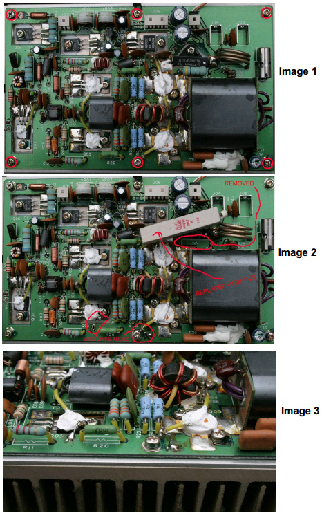
Eventually with all new components installed and new thermal compound under the transistors, we were ready to switch on. The finals idle current was adjusted without trouble but the driver current was extremely high and would not adjust at all. After rechecking everything again and soldering on an odd pair of diodes in place of D7003 & D7004 everything worked. I mounted the replacement diodes in place of the originals and switched on again. (Image 1 & 2)
Mounting these correctly resulted in the original overcurrent symptom recurring. It turned out that the solder lug which holds down Q7006 was intermittent! Although it was firmly tightened down, gentle flexing caused the earth bond to come and go.
I soldered a short length of wire from this lug to the PC board earth plane and did the same to the diodes in the final stage as well. Switch on, press the MOX button and NO SMOKE! The idle current was adjusted to give 260 millivolts across R7014 (100 Ma) and now the rig worked just the way it should. (Image 3).
The driver idle current is measured by noting the voltage drop across R7014. If this is a 0.4 ohm, you should have a 40 millivolt drop. If it is a 2.7 ohm, you should have 270 millivolts. The final idle current is adjusted in the same way, measuring the drop of 6 millivolts across R7027 (0.025 ohm) while adjusting VR7002.
After this exercise I took a look at my own FT1000 PA unit so as to modify it before it was too late. I discovered that all the all the PC board mounting screws were loose. If the screw holding the diode network in the final stage were to fail, goodbye finals! I suspect that there are many more rigs out there with the same potential problem. While the covers were off, I checked the tightness of all the other PC board mounting screws.
If you have the ability and knowledge to carry out this modification and screw check – do it before it is too late. The rig has been tested on air for some time and has shown no sign of failure. As R7014 is higher in value than the original, it produces slightly more heat than the original 0.4 ohm resistor. This is normal.
The pictures show which screws need checking and where to fit the earth links. Do not attempt this procedure if you are not fully competent and do not have the necessary skills and tools.
Peter ZL2LF
[email protected]